RF remote slave flash?

Dippy

Moderator
"..into an AND gate with the RF signal. Then an RF pulse arrives and the flash goes off."
- So that means ANY noise/pulse from the RF module after it has been 'primed' (with pre-flash) may trigger it. Mmmm...

"...ignores future flashes" - Goodness, is this a tachyon flash system?

"I'll think about this some more." - excellent idea :)

By the way, 2 questions.
1. What is the average duration of the flash?
2. Where does it happen time-wise compared to the shutter operation?
 

moxhamj

New Member
Re, "any noise", I agree Dippy and we still haven't really solved that one. Am assuming that a ranch in Texas with cornfields doesn't have too much RF interference but that may be incorrect. I can say that where I live which is 1km from the nearest suburbia is very quiet on the 315 and 433 Mhz bands. Just white noise. But then I remember the problems Stelios had with the ham operator next door!

If there is interference, then some sort of definite data packet needs to go through. The absolute minimum might be "UUAB" or something - still quick at 2400 baud but maybe not quick enough.
 
Last edited:

212

Senior Member
Nobody within 1km here either, and the only ham operators would be the local pig farmers :)

ooops...I forgot about the serin hang. I was hoping to use the same chip to keep the flash topped off too...nope.

The flash has a duration of 1/1,000th second or shorter, and I know the cameras all have a shutter lag...time between pressing the shutter button and the actual shuttering of the picture. I don't have any way to time that other than trial and error and narrowing it down.

OK...if I'm going to have two chips on the receiving end, then I might as well go with the 2262 and 2272 encoder and decoder to tell the receiving end Picaxe to fire the flash and recharge it.

I'm playing with writing a camera controller code right now, so I can try this out for size. I'll use an output pin to light an LED, then I'll connect the RF and work on getting the timing right. I'll light another LED with the receiving Picaxe to test things because those flashes do light you eyes up after a few hundred tries :)
 

212

Senior Member
ummmm...one question while you are here (whoever might be reading this) The camera will be triggered by a PIR circuit, and I need a walk test to make sure the camera is pointed where I want it. To do this we have an LED light up when we walk by, but only for a minute or so, then it goes into regular picture taking mode. I have done camera control before, but no walk test. Soooo...how do I end the walk test after a minute???

low 0
low 1
low 2
low 4
disablebod

warm_up:

high 0
pause 5000
low 0
goto walk_test


walk_test:

if pin3 = 1 then
high 0
pause 1000
low 0
pause 1000
endif
goto walk_test
 

212

Senior Member
Sorry...I missed answering the power consumption question. Just a regular slave flash, without the RF will go 4~8 weeks on 4 AA 2500 ma batteries...depending on how many flashes occur. But the receivers I have use 200ua all by themselves, so I'll be using bigger batteries I think. I'll also be turning everything off during the daytime, so that will help some.
 

hippy

Ex-Staff (retired)
For walk testing ...

Code:
StartWalkTest:
  timeout = 600 ' How many 100ms - 600 x 100 = 60,000ms = 60s
  Do While timeout > 0
    If pin3 = 1 Then : High 0 : Else : Low 0 : End If
    Pause 100
    timeout = timeout - 1
  Loop
  Goto NormalUse
 

212

Senior Member
Thank you very much!...very much! I had seen something written along those lines somewhere, but could not find anything in the manuals saying Picaxe does that. I been saving bits and pieces of code to work with on my projects, that fits in real nice :)
 

Dippy

Moderator
Re: Noise. Well, 212 had better check the module he's using. My oscilloscope leads aren't long enough to check from UK to USA but some modules give out noise on the RF Out when there is no signal due to large AGC factor.

Do we know the maximum baud rate his RF modules can operate at? Obv, faster baud=faster response. NSS.

I honestly don't know how code can be developed until the electronics/physical stuff has been sorted and tested.
 

moxhamj

New Member
Dippy, you are right. This goes back to the long standing (and unresolved) problem of programming a picaxe via radio. It is the difference between the radio modules and a true radio modem. Radio modules transmit AC - put in a square wave of audio frequency and out comes a square wave. A modem transmits true DC - put in a low, and out comes a low - forever. Modems work by having carrier tones of different frequencies. And if the carrier tone is an audio frequency the transmit time will be slower. It may take quite a number of tone cycles for the receiver to lock on. PLLs and all that.

But I wonder if we can do some picaxe based digital filtering. Could we use pulsin and pulsout? Are they fast enough? Send a pulse of a fixed narrow width, pulsin fires, if the time is between two set values then the pulse was valid. White noise will still trip it regularly but what are the chances of a pulse being the right length? Actually, probably quite high, but what about two pulses?

Or maybe it is too complex. Maybe just send a very short serin serout eg "UA". U to settle and A as the qualifier. At 2400 baud this is only a few milliseconds.
 

Dippy

Moderator
Why not arrange it so that when the preflash is sensed it sends a signal to RxPICAXE to say 'Get Ready' which puts the RxPICAXE in a Serin Wait state. The genuine flash could send the desired coupla bytes. You should't need gret pile of Us as a preamble. I've rarely needed more than one preamble byte.

Using the 'wait', would be quicker than any IFFing/faffing around with manual testing of Data.
And select a PICAXE which can Serout/Serin Data at a higher baud too. Stop penny-pinching, buy the gear appropriate for the job!!

Digital filtering would be SSSOOOO slow.

And as most people here seem obsessed about saving a few pennies (and consequently buying the cheapest stuff ever invented on Ebay) then I can hardly see the likely purchase of a radio modem arrangment.
 

moxhamj

New Member
Hmm, two bytes at 2400 baud is 1/120 th of a second. Faster than the blink of an eye. And, like dippy says, go to 4800 baud and it is even faster. I agree with dippy - serin with two bytes could be the most practical option.
 

212

Senior Member
I think what I've decided to try first, is to skip detecting the pre-flash and flash and just time the RF trigger signal to the camera shutter press. Not knowing anything at all about what my RF units are capable of as far as speed etc, I figure I can try it this way first. The idea has gone from just an RF slave flash that detects the flash from the camera to one that I may also use with a camera that has no flash at all...like a "toy" digital for kids. The RF remote part is not really needed to get a night picture, but having the flash apart from the camera keeps the animals eyes from looking like a couple of big yellow saucers. I have had cameras where you can not even perceive the time between shutter press and shutter, and I have one here that takes over a second too.

I bought the RF as part of a driveway alert system, I like them because the range is sufficent...about 400 ft, and the PIR part is pretty reliable too. I can use the PIR part of them to sense movement and tell Picaxe to turn the camera on and take the picture, and I can use the RF to operate the remote flash too...plus, they have all the regulators and lots of cool extra parts. dippy, I'd be more than happy to send you and Dr_Acula a set of them to play with if you are interested in looking at them.
 

Dippy

Moderator
Love to, but sadly I've got no time. It's one of those things that may work fine, but may take days to tweak. On the other hand a PIR driveway alert doesn't need to be superfast and the Tx/Rx may simply not be up the task. This is one reason I tend to open that wallet up and buy products specifically for the task, with a known spec (i.e. Data Sheets in English), from a quality (reliable/consistent) manufacturer. I'd rather spend an extra tenner than spend 3 weeks wrestling.

In some cases, with quality products, you can get something up and running quick rather than spending weeks possibly getting nowhere. How long has this thread been going? I could have got this running in 2 days with the right gear.
On the other (other) hand, your stuff may be up to the task and it has provided valuable experience for the future - so don't take any notice of an impatient old mugger like me :)


Maybe if DrAc shut surgery for a day or two....?
 

Mycroft2152

Senior Member
Love to, but sadly I've got no time. It's one of those things that may work fine, but may take days to tweak. On the other hand a PIR driveway alert doesn't need to be superfast and the Tx/Rx may simply not be up the task. This is one reason I tend to open that wallet up and buy products specifically for the task, with a known spec (i.e. Data Sheets in English), from a quality (reliable/consistent) manufacturer. I'd rather spend an extra tenner than spend 3 weeks wrestling.

In some cases, with quality products, you can get something up and running quick rather than spending weeks possibly getting nowhere. How long has this thread been going? I could have got this running in 2 days with the right gear.
On the other (other) hand, your stuff may be up to the task and it has provided valuable experience for the future - so don't take any notice of an impatient old mugger like me :)
There 3 kinds of projects:

Cheap projects
Learning projects
Completed projects

As Dippy said, spending a few extra dollars (quid, loonie, lira) on the right gear makes a world of difference.

So next time, dig out Occam's razor and shave off some time. (Ouch, that was a pretty bad one)

Myc
 

Dippy

Moderator
Six.

The "I'll just tell everyone about my great idea but never do it" project.

This has the effects of:-
A) Giving others the impression of genius.
B) Provokes people to make suggestions for design and code so that the originator's overworked cerebellum can have a rest.
C) Wasting everyone's time except the originator who has gone to the pub for three weeks whilst everyone else has an anorak war - usually resulting in the thread going completely into Red-Herring-Mode ending up in a tedious political discussion.

Boy, have I seen a few of these here over the years.
 

212

Senior Member
Well, I'm for sure cheap, don't know much so I need to learn, and I hardly ever finish anything...because I'm cheap, dumb, and easily distracted.

Naw...I have been learning a lot from you guys and I appreciate your help very much. I'm not the average age person that comes here asking how to complete a school project, I'm an old uneducated man that wants to learn this for pure enjoyment. I've spent hours and hours on here just reading and admiring how knowledgeable and helpful you all are as a group, and hopefully I can give back a little someday.

This, and all the projects I have asked for help on, are works in progress. As I learn more here, I will add to and improve them, so I may never say "it's done".
 

212

Senior Member
Hey hippy...you got me to think again didn't you!

Yep, I got it working, thanks for not making it too easy too :)
 

moxhamj

New Member
Re "dippy, I'd be more than happy to send you and Dr_Acula a set of them to play with if you are interested in looking at them."

Sorry, am a bit busy with work - 98 hours last week, though some of that is working after hours where there are gaps between patients. So that does mean I can post ideas etc on the forum as there is always a computer nearby, but I don't have so much time for prototyping and experiments :(

In my currently tiny bit of spare time I am continuing with RF module experiments. I'm interested in some of the "types of projects" above - this problem isn't necessarily solved with money. More with cunning. For instance - big money tends to equate to big equipment which equates to big current draws which doesn't work so well when things are running on batteries. (But I'm sure someone will disprove this by finding a very expensive device that draws microamps! Maybe from NASA or something. How much did they spend on that biro that writes in space when a pencil would have done the trick!)

I've currently got a board almost ready for production and it has 3 picaxes on it. One is the master picaxe (18X). One is an 08 which listens all the time to the RF module and only outputs when a proper packet arrives. This is in effect a digital filter, and a very cost effective one at that. The third picaxe is a watchdog 08 picaxe and resets the 18X if it doesn't get a pulse every second or so. This is a workaround for the serin hang problem, and is necessariy once a module starts scanning more than one input (eg 3 RS232 ports, and a 315Mhz RF module/Hope 433Mhz module all at the same time).

Your problem is a bit simpler in that the data is only one way. And I think the two byte solution is well worth some experiments. It should be pretty easy to breadboard up with just a wire link and test if it is fast enough.
 
Last edited:

Mycroft2152

Senior Member
Dr A,

I was not suggesting just throwing money at a project, but rather using the right tools for the job.

You CAN cut down a tree with a steak knife, but a chain saw does a much better job.

Myc
 

moxhamj

New Member
True, Mycroft2152. Actually I have put quite a lot of money into this project. There are lots of dead ends lying around that were quite expensive. It is just in this case cheaper things worked better. But that isn't necessarily always so. And sometimes it is hard to know what the right tool actually is, especially when it comes to some of the over optimistic range specs for RF modules! Speaking of chainsaws and living on a rural property, I also have some expensive broken chainsaws lying around. And some broken cheap ones. The expensive ones cost 3x the price and last 2x longer. Sorry, bit of a pet hate of mine - buying expensive stuff and finding it is only a little bit better than cheap stuff. Rant over. Going back under rock now...
 
Last edited:

Mycroft2152

Senior Member
True, Mycroft2152. Actually I have put quite a lot of money into this project. There are lots of dead ends lying around that were quite expensive. It is just in this case cheaper things worked better. But that isn't necessarily always so. And sometimes it is hard to know what the right tool actually is, especially when it comes to some of the over optimistic range specs for RF modules! Speaking of chainsaws and living on a rural property, I also have some expensive broken chainsaws lying around. And some broken cheap ones. The expensive ones cost 3x the price and last 2x longer. Sorry, bit of a pet hate of mine - buying expensive stuff and finding it is only a little bit better than cheap stuff. Rant over. Going back under rock now...
Been there, done that!

Too many times you re only paying for the "name" when it is actually made on the same assembly line as the no name versions.

After all, someone has to pay for all the advertising.
 

moxhamj

New Member
"..made on the same assembly line as the no name versions."

They do that with medicines too. I've been to a factory and seen it!
 

Mycroft2152

Senior Member
"..made on the same assembly line as the no name versions."

They do that with medicines too. I've been to a factory and seen it!
My daughter is a pharmacist, her stories about the pricing of the meds are "hair raising", and we're just talking about the cost to the paharmacy versus the retail prices.

In the US, the major department stores usually have a pharmacy. They have been selling 30 day supply of generics for $3.99

They are still making a profit and as an added bonus, the average shopper buys more reguar merchadise while in the store at the same time to pick up the meds.
 

Dippy

Moderator
It wasn't a 'Shadow' factory in China was it?

Well, there are differences between cheap generics under license / legal copies and illegal (or unhealthy) fraud copies aren't there. Zantac is a common example.

sub Rant(ByVal Moan as Byte)
dim Theory as boolean

Actually this cheap vs expensive argument is so weird.

A cheapskate builder friend of mine always got his cheap tat and didn't care how long it lasted.
His theory he gave to me is:-
"I can buy 10 Anonymous Chinese Cheapo cordless drills for the price your £250 (Swiss Made) Bosch. So cheap , they're disposable."

Theory = True.
Then he had to do a bit of work miles from anywhere doing up his country house in rural France. His ACC conked. A nice 40 mile round trip was required to get a new Cheapo drill. Two gallons of fuel and half a day wasted. And another landfill hole being topped up with cheapo tat.

This is precisely how these Cheap manufacturers survive. It's SO cheap you don't bother with warranty. You bin it and buy more tat. What a waste. And simultaneously the quality manufacturers suffer because the world is full of tightfists who don't care about quality. Save a quid and that can go on beer or some toy with buttons.

BTW: He has now spent £300 on a Bosch and it has yet to break after 3 years - and he is a clumsy git, so it's a good test.

So carry on buying cheap tat by all means. I won't.

End sub
 
Last edited:

papaof2

Senior Member
"BTW: He has now spent £300 on a Bosch and it has yet to break after 3 years - and he is a clumsy git, so it's a good test."

I saw an excellent example of this when the garage door was replaced. The installer dropped his cordless drill (a Bosch) 9 feet to the concrete below. The drill and battery each went its own way. The installer calmly picked both items up, put them back together, and went back up the ladder without testing whether it still worked. Obviously this had happened before and he was confident that it would still work.

John
 

BCJKiwi

Senior Member
The point here is that many (if not most) "never regretted buying quality", as the saying goes.

However, many brand names that used to represent unquestioned quality, either now put out rubbish or have 'home' lines that are rubbish.
Other brand names now don't make anything themselves but subcontract all their work to the cheapest bidder run by run resulting in low and inconsistent quality.
The 'better' brand names that also subcontract their manufacturing maintain specification and quality control.

The big issue is how to pick the products that really are quality and reliable - caveat emptor!
 

212

Senior Member
I have been working on the camera controller part of the project. I still need to figure out exactly when to trigger the flash, but I needed to get this working so I can do that. I will post a schematic when I get something presentable, right now it is chicken scratch.

Anyway, I tried this tonight, and I think I am pretty close with it. I put a meter between the circuit and battery, and I'm confused??? The first time I power the thing up, and after it runs the walk test, it settles down to using about 22ua. But...once I trigger it to take a picture, it ends up at about 100ua or so when it is finished. I took some liberties here, not knowing what I'm doing. I wonder if anyone might see something I need to correct??? Sorry about the way it reads on here, it looks good in my editor?

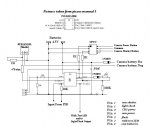
'Using Picaxe 08M chip, I will attempt to build a camera controller.
'This controller will use a PIR detector to put pin3 either high or low to
'trigger the sequence of events, depending on which PIR circuit is used. The
'intention is to connect the cameras batteries to the camera on first detection,
'and otherwise leave them disconnected. This is for use with some cheap cameras
'that will run the batteries down if left in the camera for extended periods, or
'for those that might occasionally lock up..
'This may not work for some cameras, as they will ask you to set the time and
'date before letting you take a picture...and most will loose the time and date
'with the batteries out. The battery connect feature can be used for powering a
'slave flash instead, with a slight mod in the code.

'I will also be trying to time a flash unit to fire when he picture is taken.
'This is to use a camera that either has no built in flash, or to be used with
'that has one, but can be turned off. This will solve the issue of batteries
'being drained from keeping the cameras flash charged up too. This is work in progress!


low 0 'CDS power and cam power button
low 1 'cam shutter and light check
low 2 'flash and walk test LED
low 4 'pin 4 camera battery connection


disablebod 'this turns off brown out detection to save power

warm_up:

high 2 'this lights the walk test LED and flash on power up
pause 5000 '5 second pause
low 2 'turn off walk test light
goto walk_test 'go to walk test...duh


walk_test:

w0 = 60 '6 seconds...was 600' How many 100ms - 600 x 100 = 60,000ms = 60s
Do While w0 > 0 'walk test lasts till timer is timed out
If pin3 = 1 Then 'pin3 goes to the PIR, when PIR detects motion...then...
high 2 'light walk test LED to show detection
pause 1000 '1 second pause
low 2 'turn walk test LED off

Else 'if no motion is seen this time, still count down the timer anyway
Low 0
End If
Pause 100
w0 = w0 - 1 'deducting one second from walk test time
Loop 'this just says to keep the walk test running till timed out
Goto CameraMode 'walk test finished, now go to regular camera mode


CameraMode: 'camera is armed and ready to take a picture when motion is seen

poke $8f,%00000000 'this will slow the chip way down to 31 kHz to lower the power use
if pin3 = 1 then check_light 'this line says if motion is seen, go check if it is night or day
goto CameraMode 'no motion...keep watching for it

check_light:
setfreq m4 'bring the chip speed back up to 4mhz
pause 10 'waiting 10/1000 second
high 4 'turning on camera battery battery power to camera


'xxxxxxxxxxxxxx
input 1 'change pin 1 from an output to an input pin...untested
'xxxxxxxxxxxxxx

pause 10 'waiting 10/10000
high 0 'turn on CDS power and camera power on pin
readadc 1,b1 ‘read the value of CDS to see if it is daytime or dark
pause 100

'xxxxxxxxxxxxx
low 1 'turn pin 1 back to output and turn it off...untested
'xxxxxxxxxxxxx

pause 500 'wait 1/2 second while camera powers on
low 0 'turn off CDS power and camera power on pin
if b1<100 then no_flash &#8216;range 0-50 = 50...daytime
if b1>100 then flash &#8216;range 50-100 = 50...night time


no_flash: 'this runs in daytime

pause 2000 'time delay after cam powers on before shutter press
high 1 'turn on shutter button and hold
pause 500 'for 1/2 second
low 1 'turn off shutter button
pause 30000 'waiting 30 seconds for picture to be saved
high 0 'turning camera off
pause 500
low 0
pause 1000
low 4 'turning off camera battery power to camera

goto CameraMode


flash: 'if it is night time, we will use this

pause 2000 'time delay after cam powers on before shutter press
high 1 'turn on shutter button and hold
pause 500 'for 1/2 second
low 1 'turn off shutter button


'xxxxxxxxxxxxx
high 2 'turning on flash/array
pause 1000 'will need to be adjusted to get it in sync with shutter
low 2
'xxxxxxxxxxxxx


pause 30000 'waiting 30 seconds for picture to be saved
high 0 'turning camera off
pause 500
low 0
pause 1000
low 4
pause 5000 'this pause is the picture to picture delay time

goto CameraMode 'return to CameraMode and wait for motion again
 
Last edited:

moxhamj

New Member
Very impressive. Lots of us are watching this project as you could be on to something quite useful in other applications. I'd like to snap a picture of a platypus which I have only ever seen once in my local river.

I have no idea why the current changes - maybe the picaxe consumes more running different instructions. But 100uA is very low. Can you live with that - bigger batteries etc? I'm working with a minimum of 5mA for a solar radio repeater - a pain it is so high but solveable with a 7AH SLA which will run for over a month.
 

Dippy

Moderator
I can't help on the current question either, but 2 things to remember:-
1. There was that business with disable/enable BOD being reversed/inverted (would suggest POKE to make sure you've got it right)
2. If you've set pins input/output low/high to external circuitry then that may affect current consumption.

Also, from the power perspective, I notice you have 30 second delays. If you can stand the timing inaccuracies then Sleep would give lower the average power.
 

212

Senior Member
Thanks for the replies, and for the kind words. I'll sure do that Dippy, thanks. I'm not very concerned about the 100ua, it is the fact that it goes up after taking a picture. I put an LED on the cam battery control pin, and one on the walk test, so I could see if that worked. Both seem to be functioning. I have an opto to control the camera functions in the circuit already, but have not connected the camera yet. I wanted to watch for sparks and smoke before risking my camera...whew...no smoke!

I think :)...I need to make sure my pin 1 isn't staying an input, that might explain the power issue huh. But if I try it now, I won't get to work on time and who is going to buy me more Picaxes if I loose my job???


'xxxxxxxxxxxxxx
input 1 'change pin 1 from an output to an input pin...untested
'xxxxxxxxxxxxxx

pause 10 'waiting 10/10000
high 0 'turn on CDS power and camera power on pin
readadc 1,b1 ‘read the value of CDS to see if it is daytime or dark
pause 100

'xxxxxxxxxxxxx
low 1 'turn pin 1 back to output and turn it off...untested
'xxxxxxxxxxxxx
 

Dippy

Moderator
212, depends on your circuit. Sometimes it is beneficial to turn it into a high impedance input. As long as floating on external components isn't a problem. Low or High (output mode) can pass current. I haven't seen your circuit, so it is just a thought to keep in the bonce for where and when applicable.
 

212

Senior Member
I put my code into an 08M on my little project board. The only extra component added, besides the basic download circuit, is a 10K resistor grounding pin3. I get the same results as I did with the code running the full circuit....which I will still draw.

I still get the same 20 something micro amps, until I trigger the input to run the code. After the code goes through all the hoops, the power goes up 5 times what it was before running it. I took out pieces of the code till I found what is making it use more juice.

"readadc 1,b1 &#8216;read the value of CDS to see if it is daytime or dark"

That's it! Even though I later make pin 1 an output, and use it for another operation, it still makes the power go up. I even made b1 = 0 later on, to see if that helped...nope. Like I said, the 100 or so micro amp usage is not that big a deal, but if it can be reduced easy...why not do it? Again, there is nothing connected to pin 1 on my little board.

By the way, I think it's going to work :)

Any ideas on how to do that???
 

moxhamj

New Member
You might be on to something interesting here! Not sure what the answer is. But interesting nonetheless. Can you do another quick test - does it go even higher if you do a "readadc 2,b1"?
 

BCJKiwi

Senior Member
"The only extra component added, besides the basic download circuit, is a 10K resistor grounding pin3"
"Again, there is nothing connected to pin 1 on my little board"

There should be something connected to all inputs - e.g. 10k to ground.

Even though the port is being switched, there could be strange internal circuits arising from floating inputs.

Suggest you put 10kRs on all the unconnected inputs and see if that changes the current draw.
 

Dippy

Moderator
First, do as BCJ says. Floaters can be nasty :)

This is just a thought as I know nothing about how the PICAXE firmware operates.

Try POKE $1F,0 (= POKE 31,0) after the READADC.

If the ADC module was left enabled after the READADC then this would switch it off. (The above simply sets ADCON0 to zero. When ADCON0.0 is set to zero it shuts off the ADC).
Having said that I would have thought that using it as a digital I/O afterwards would have done that anyway, so this is simply clutching at straws and probably won't do anything.
 

212

Senior Member
Give Dippy the beverage of his choice! You nailed it Dippy, I have no idea where you got that from, as I'm still in kindergarten, but it solved the mystery. Now I get about 22ua when the code finishes, and is just sitting there...basically doing nothing.

Dr_Acula, I see no change in power usage when I "readadc 2,b1". I tried changing what I had (readadc 1,b1) to that, and I added it in with what I already had too...same results. I tried it before and after adding Dippys suggestion too...same same.

BCJKiwi, I am using an 08M, and have all pins as outputs except for pin3. I do appreciate the reply though, I need to be reminded about things at my age :)

Now I know my wiring is not the cause of the excess current being used, I will finish the schematic. And...I have an idea about how to find the right timing to fire a flash, timed to the shutter press on my cameras. I'll write something to keep trying over and over automatically, but changing the delay 1/1000 second each time. Then I should be able to look at the pictures and count through them to where the flash lightens the picture.
 

212

Senior Member
I had this circuit in my mind, and it works the way I wanted it to on a breadboard. But now that I have it drawn out where I can see it better, I wonder why it works :) Any comments or better ideas welcome of course.

Oh, and I got the camera to take a picture of an LED, lit up for only 1ms, but as it got darker the cameras timing changed a little. Hopefully I can get the timing just right to fire a flash at the right time when it is dark enough to need it. Then I can work on the RF part again. If not...I'm back to having to build a first flash ignore program like I began with.

I drew this with "Paint" I sure need to learn how to use a proper schematic program someday.
 

Attachments

Top