Resurrecting the dead!

cdngunner

Senior Member
OK.

As I have mentioned before I am trying to replace an old 18 pin pic with the new 18M2 on an exisitng OLD board.

I also mentioned that I suck at electronics........(no kidding huh!)

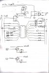
To keep hippy, dippy, kippy, and anyonle else ending in ippy happy, I have tried to draw the circuit from the old board. (see below)

I do have a few questions about the TIP122. Does the TIP122 and the R/C circuit look correct? Keep in mind that there are two separate power supplies. One for the motor and one for the controls.

Second question, are the legs on all TIP122 the same? I have a couple old boards where the collector and emmiter legs are swaped, same PCB layout though.

Thanks ahead of time.
 

Attachments

Last edited:

MartinM57

Moderator
Second question, are the legs on all TIP122 the same? I have a couple old boards where the collector and emmiter legs are swaped, same PCB layout though.
I've never seen a common device from different manufs with different pinouts - would be a nightmare if that happened. From a quick squiz at TIP122 datasheets from different manufs they are all the same - Pin1=base, Pin2=collector, Pin3==emitter e.g. http://www.datasheetcatalog.org/datasheet/fairchild/TIP122.pdf
 

Dippy

Moderator
"Second question, are the legs on all TIP122 the same? I have a couple old boards where the collector and emmiter legs are swaped, same PCB layout though."

- I don't know. I haven't checked every TIP122 and I don't plan to :)

But, if the statement "I have a couple old boards where the collector and emiitter legs are swapped" is true then have you not answered your own question .... ??? :confused:


PS. Martin, aren't you meant to say 'legout' on this Forum ? ;)
 

cdngunner

Senior Member
"Second question, are the legs on all TIP122 the same? I have a couple old boards where the collector and emmiter legs are swaped, same PCB layout though."

- I don't know. I haven't checked every TIP122 and I don't plan to :)

But, if the statement "I have a couple old boards where the collector and emiitter legs are swapped" is true then have you not answered your own question .... ??? :confused:


PS. Martin, aren't you meant to say 'legout' on this Forum ? ;)
Things are not as obvious to me as they may be to you. I wish I was as smart as you but alas my parents genes have let me down.


Come on, I drew you a nice circuit. Can you answer the first question, please :)
 

Andrew Cowan

Senior Member
I don't quite understand the circuit, but it looks like the TIP122 controls the speed of the motor, and the relay the direction.

The TIP122 is an NPN transistor - to control the motor, I'd expect the emmitter to be tied to 0v, and the collector to the -ve motor lead. In the configuration your circuit shows, I'd expect a PNP transistor - clearly something I don't understand is going on! No idea what the RC network is for!

The 1K looks like a pullup for the 2222A's collector - thus making an invertor to the base of the TIP122.

Andrew(ippy)
 
Last edited:

cdngunner

Senior Member
Funny eh!

This was designed by engineering students at the University of British Columbia.

Yes the tip is being used as a simple on/off for the power to the motor(s)

I just didn't understand why they tied the collector of the PN2222A to the power side for the motors via the R/C. Filter of some sorts is my only guess.

Gonna yank the board with the cross-legged TIP out of the box to see if they screwed with the traces on the back.
 
Last edited:

Dippy

Moderator
Andrew makes a good point. In my shock I hadn't seen that. I was exhausted after spending 20 minutes looking at TIP data sheets for you.

Using an NPN Darlington like that (i.e. as a high side switch) is poor and VERY inefficient. In fact I'd be surprised if it could do much with any degree of oomph. Have you never seen how an NPN tranny behaves when used high-sided? Base voltages wrt E voltages and all that?

They may have been 'engineers' but I guess the bar was open (TeeHee).

As Andrew says it should be a PNP , better still a P chan MOSFET.
But who am I to question university engineers...
I'll leave P MOSFET theory to Manie as he has absorbed all my magic.:eek:


My auto catflap opener was designed by a bloke from NASA - he cleaned the bogs :rolleyes: I'm rarely impressed by name-dropping...
 
Last edited:

cdngunner

Senior Member
Andrew makes a good point. In my shock I hadn't seen that. I was exhausted after spending 20 minutes looking at TIP data sheets for you.
and I appreciate that.....

Using an NPN Darlington like that (i.e. as a high side switch) is poor and VERY inefficient. In fact I'd be surprised if it could do much with any degree of oomph. Have you never seen how an NPN tranny behaves when used high-sided? Base voltages wrt E voltages and all that?
Showing my degree of ignorance, I only understood half of what you just said

They may have been 'engineers' but I guess the bar was open (TeeHee).
A lot of what they did made me ask WTF!

As Andrew says it should be a PNP , better still a P chan MOSFET.
But who am I to question university engineers...
I'll leave P MOSFET theory to Manie as he has absorbed all my magic.:eek:


My auto catflap opener was designed by a bloke from NASA - he cleaned the bogs :rolleyes: I'm rarely impressed by name-dropping...
Well everytime I drop the "Dippy" name people stand open mouthed with amazement.......;):D


p.s. maybe they saw the errors of their ways and tried to fix the already made boards in ref to the crosslegged TIP
 
Last edited:

Dippy

Moderator
Amazement? Dear Lord, they probably run screaming to their therapists.


Tell the engineers about PNPs and P Chans.
I haven't got time to type, all I can say is try an NPN as a high sided switch and see what happens as you increase the base volts and as you load up Ic or Ie.


Just remember; you can make a brilliant high-sided switch with a P Chan and a pretty good one with a PNP. When you start getting into 'power' conditions you have to pay carefeul attention to currents in base and Hfe.
This is why P Chan MOSFETs (or purpose-built HSS) are used in preference in many, manie Apps.
It IS possible to use N Chans but it requires careful gate driving and I would avoid distractions where a P Chan is perfectly feasible.(i.e. let's avoid too many tangents on a simple design aspect).


"WTF" ??
I'd have said "I'll have a pint of whatever you lot have been drinking!" :rolleyes:


My final tip of the day: wherever possible/practical avoid Darlingtons and use MOSFETs. And in little things use simple BJTs instead of darlingtons.... wherever possible. Vce ... and I don't care what anyone says to the contrary.


"p.s. maybe they saw the errors of their ways and tried to fix the already made boards in ref to the crosslegged TIP"
- maybe ... why not ask them ..... ?
 

techElder

Well-known member
Well, I'm not a professional designer, but ...

The relay "A" is a reversing relay for the motor direction.

The transistor "TIP122" is configured to be a PNP type high-side switch with it's base pulled low and controlled by the "PN2222A". Some motor speed control could be implemented, but it would be difficult to perform and would depend on the motor components.

The RC circuit is there to provide a slow turnoff function for the motor.

Whether the components are drawn correctly or are labeled correctly is beyond the scope of my comments.
 

Dippy

Moderator
"Well, I'm not a professional designer"
-- meeeaoww ;)


Well, it's all very confusing. A TIP122 is a Darlington NPN and the the drawing shows an NPN bjt and any NPN device would be limp in that position.


Also, I hadn't followed those 1 and 2 and A and B bits at the bottom before.
Those PN2222A NPNs triggering the relay are wired as high sided.
Not good.
Wire them as low sided as shown in PICAXE manual then you can lose the associated diodes.
Were they electronic/electrical engineers or plumbing engineers ? :)
(I'm just kidding).


Needs a bit of a revamp to make it good.
So, good luck with it.
 

cdngunner

Senior Member
"p.s. maybe they saw the errors of their ways and tried to fix the already made boards in ref to the crosslegged TIP"
- maybe ... why not ask them ..... ?

They are all DEAD:eek::eek:

No seriously. These boards are 20 some odd years old. Unfortunately I keep getting requests to fix the damn things. For the most part most of the problems were easily fixed, now they are starting to lose the pics for some reason. I want to be able to just pop in the 18M2 and send them on their way.
 
Last edited:

Dippy

Moderator
Ah, I see.
Maybe your schematic interpretation isn't quite wrt your question about TIP pinouts ?

Sorry, I really can't help on this.

I have a spare Crystal Ball if you wish to get in touch with them.
 

cdngunner

Senior Member
Ah, I see.
Maybe your schematic interpretation isn't quite wrt your question about TIP pinouts ?

Sorry, I really can't help on this.

I have a spare Crystal Ball if you wish to get in touch with them.
You know for the most part I have always been able to fix things without knowing exactly how they work.

I'm getting into this electronic thing (ewwww) and not knowing how things work or how they are put together is starting to bug me.

I'd like to be able to say.

"theres your problem, the precharge pump on your flux capacitor is not phasing your core drive correctly" and know what I am talking about.

In short, I want to be just like you.... lmao!
 

eclectic

Moderator
They are all DEAD:eek::eek:

No seriously. These boards are 20 some odd years old. Unfortunately I keep getting requests to fix the damn things. For the most part most of the problems were easily fixed, now they are starting to lose the pics for some reason. I want to be able to just pop in the 18M2 and send them on their way.
What was the
original chip
that you want to replace?

It wasn't a Picaxe.

e
 

eclectic

Moderator

cdngunner

Senior Member
Genuinely naive questions:

You have a 20 y.o. board, with a "broken" Pic16C.

Do you have the original programs for the Pic16?

Or, what exactly did the original circuit do?

How do you plan to replicate the original operations,
using the 18M2?

And, separately:
http://khup.com/view/19_keyword-tip122/unisonic-technologies-co-ltd-tip122.html

It may be a Red Herring,
but it does have a different pinout / legout.
e
it is a very simple application as many wheeled or tracked robots are.

I should be ok writing a program to make it do all the stuff it did before.

Basic, basic,basic.

Two analog inputs to control a tracked vehicle skid steer style.

joystick gives me 0-5 vdcnin both x and y axis

0 would be backwards 2.5 neutral and 5 forwards with a deadband around the 2.5

left right would be almost identicle except that it would also flip the relays to run the motors in opposite direction.

piece-o-cake.

Like I said, I could easily enough program the picaxe and slap it in there, but I would like a better understanding of what is actually happening.
 

cdngunner

Senior Member
OK, the cent is descending.

It's fixing control boards on
one of your company's cleaning robots.

e
Actually, its not mine at all. Unfortunately I have inherited fixing these things since the original maker went under some ten years ago.

For mine I buy off the shelf controllers and slap them in. Why muck around when everything you need is on a $90.00 board.

I want to get "fancier" thats why I turned to Picaxe. I want to start integrating sensors and stuff. My company is only a few years old and I am trying to grow it. Difficult now-a-days when shit comes in by the boatload from China for one tenth the price
 
Last edited:

fritz42_male

Senior Member
Instead of repairing the damage, why not reverse engineer from requirements? You could use an off the shelf Picaxe board such as a CHI035 - maybe take the FETs off board and use decent heatsinks on them.

What current does the motor take on startup? What EXACTLY does the original setup do?

A CHI035 solution shouldn't take long to bolt in and program
 
Last edited:

cdngunner

Senior Member
Instead of repairing the damage, why not reverse engineer from requirements? You could use an off the shelf Picaxe board such as a CHI035 - maybe take the FETs off board and use decent heatsinks on them.

What current does the motor take on startup?
LOL

Not that I havent thought of that. My customers are CHEAP, probably Scottish.

They will love me more if I can fix their problem for under $10 and hopefully one day buy a robot from me when the old is no longer fixable.
 

Minifig666

Senior Member
LOL

Not that I havent thought of that. My customers are CHEAP, probably Scottish.

They will love me more if I can fix their problem for under $10 and hopefully one day buy a robot from me when the old is no longer fixable.
Once again the stereotypes are back home!

If they're looking for cheap, could you use a smaller PICAXE and pop a few wires from it to the socket. It'll save them quite a bit of dosh.
 

Minsik

New Member
Hi all,

Certainly this cct as drawn, looks wrong.
Could it be a TIP127 or TIP125 instead of a TIP122?

Why is there a controlled dc feed from the TIP222 and yet also from a PN22224 (1) and (A), (is there a PN22224 device?). As the supply rails are 5v and motor feed = a higher dc feed, is this a 2 speed control or what? A PN22224 device if its a PN2222 will only have a very small current rating too.

Also checking any transistor connection.
Theory says that the collector-base junction area is larger than any base- emitter junction area. In practice this works. Measure carefully on diode test with your multimeter. Lowest junction voltage drop is the c-b and higher is e-b. Common is of course the base. Small transistors will be harder to pick and dont heat them with your fingers as you struggle to make a measurement as temperature will change the reading.

In a darlington there are 2 active devices + possible protection diode across c-e and resistors. b-e as darlington will be 1.2v approx as 2 junctions in series, b-c will be junction of the driver alone. Resistors can be measured on ohms test (if low enough so the voltage wont turn the junctions on). Know your multimeter and of course all tests are with device removed from the cct. Also back to basics, use a 5v supply and a appropriate R load. Use another R 47K to bias on the darlington. Make sure it works as a transistor and not as a bowl of fruit. Darlington HFE(gain) might be 100 to 300. Thus 1ma base current will give 1-300 ma collector current. Yes transistor is good. No then connections wrong, faulty device!


Perhaps double check the cct. Did you draw it? Was it checked with some actual metering physical checks on the actual cct?

After nearly 40 years in electronic service the worst faults/problems are man made and changes from what should be there! Trust no-one, believe nothing. Fact is what counts.

Good luck.
 

cdngunner

Senior Member
Minsik.

My terrible job writing I guess. The PN22224 is indeed a PN2222A.
I believe they use the PN2222A to turn on the TIP122. On other boards they use TIP120's; I think the only difference is amperage. The motor voltage is 12vdc

These boards work. Done correctly or not. Thats the one thing that I hate about electronics ,even wrong or failing, electronic components can still work. The electrical side that I am used to either it works or it doesn't. non of this half on crap when fried ;)

I am trying to understand the schematics, I am trying to learn.

One of the things that is getting to be abundantly clear is that I need a silly-scope to go along with my meters.
 

fritz42_male

Senior Member
Not to tell you your business but if they are complaining about the cost of a new board plus Picaxe at 10 quid plus your time then they aren't customers I'd want. There is probably no-one else around who would touch a repair like this for under a couple of hundred quid minimum!
 

techElder

Well-known member
Reminds me about the joke of the body parts. All of them were bragging about how important they were to the overall condition of the body. It finally got around to the A$$H---, and the other body parts only laughed, made fun of it and dared it to show just how important it was.

So, the moral of this story is that every once in a while the A$$H--- needs to plug up and show them how important it is.
 

cdngunner

Senior Member
Not to tell you your business but if they are complaining about the cost of a new board plus Picaxe at 10 quid plus your time then they aren't customers I'd want. There is probably no-one else around who would touch a repair like this for under a couple of hundred quid minimum!
Keep in mind that "this" is not all about money.

I want to learn more about electronics and pics in general.
 

Dippy

Moderator
I reckon that your desire to learn is excellent. :)
Good on you! Teach a man to fish and all that stuff.

My worry is whether you'll learn much from a debatable design ...
(Assuming you have transposed it correctly and that's something only you can tell).

Money passing hands? Are we on commission by the way? ;)
 

cdngunner

Senior Member
I reckon that your desire to learn is excellent. :)
Good on you! Teach a man to fish and all that stuff.

My worry is whether you'll learn much from a debatable design ...
(Assuming you have transposed it correctly and that's something only you can tell).

Money passing hands? Are we on commission by the way? ;)
For you my friend, I'll give you 3% of every 5 pounds I make ;) You will be unrich like me in no time! (thats why I have a real job to feed my family)

You are probably right about learning from a bad design. But sometimes you can learn more from what people are doing wrong then you can from what they are doing right.
 

fernando_g

Senior Member
"But sometimes you can learn more from what people are doing wrong then you can from what they are doing right."

Amen!
 

Dippy

Moderator
Yes, all very clever I'm sure , but ONLY if you know it's wrong which requires other people tell you what other people are doing wrong...

e.g. if us lot hadn't told you about transistors you'd have gone through life thinking that arrangement for an NPN was a good high-sided driver. Eh?


I'd leave the philosophy to hippy and his amazing technicolour analogies if I were you ;)
 

fritz42_male

Senior Member
Keep in mind that "this" is not all about money.

I want to learn more about electronics and pics in general.
No argument there but don't give your time away at ridiculously low rates regardless of the learning you are doing. Charge a fair rate for the repair. 10 years ago before I left the UK I was charging 49 quid an hour for my IT skills and had no shortage of demand. If I learnt on the job, I didn't charge them for the learning time but I did charge them for the fix time.

Value yourself because if you don't then no other bugger will!

Oh and FYI - I learnt the hard way - got taken to the cleaners by someone who I gave a special rate to because they pleaded poverty. In the end they didn't pay their bill anyway AND still tried to get support off me and got rude when I cut them dead.
 
Top