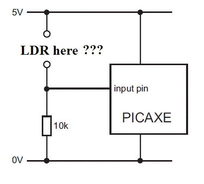
Resistance to hold an input pin low, 18M2 ?

joe paul

Senior Member
Hi Folks,

I want to use a Light Dependant Resistor to hold an input pin low when dark. With the 18M2 project board @ 4.5 volts, if the resistance of the LDR is 2 mega ohms (dark), is that sufficient to hold an input pin low by itself? (I don't want to slow down the program with a READADC and an IF/THEN.)

Thanks!

Take care, Joe.
 

erco

Senior Member
You don't need a Picaxe or other micro to do what you describe. Just use hardware: a fixed resistor with your LDR makes a voltage divider that will stay low in the dark.

Otherwise, you must code the Picaxe with readadc and if then low else high commands. Name your poison.

Edit: Buzby types faster than I do
 

joe paul

Senior Member
Hi Folks,

Thanks, Everyone, for the replies!

Please let me put this another way.

When using the AXE002U project board, if I put the LDR in the 2 pads for an input, will that keep the pin low at 2 mega ohms (dark) and high at approx. 10K (lighted)?


Thanks!

Take care, Joe.
 
Last edited:

joe paul

Senior Member
Hi Erco,

Thanks for the info! Just what I needed confirmed! (Nice video, too!)

Take care, Joe.
 
Last edited:

techElder

Well-known member
Now, (as Buzby suggests in #2) do the same experiment with a leg that has a Schmitt trigger input.
 

joe paul

Senior Member
Now, (as Buzby suggests in #2) do the same experiment with a leg that has a Schmitt trigger input.
Hi Texaschopper,

Thanks for the reply! Unfortunately, I don't understand what you are saying and I think Buzby misunderstood my question. Anyway, I got what I need right now. I appreciate the journey, but I don't need to experiment any more than I have been! :D

Take care, Joe.
 

erco

Senior Member
@Tex: It's actually harder to get oscillation than I thought. Just did a quick bench test with a multiturn trimpot and I only got oscillation when the DVM was also flickering between 1.19 and 1.20V.

Joe: Tex means that if the twilight is "just right" to hold the LDR voltage divider at 1.2V, the pin may flicker/oscillate between reading high/low. Hopefully your scheme won't allow that to happen.
 

techElder

Well-known member
The point of a Schmitt Trigger style of input is that it has slightly different threshold voltage values after an input changes logic level.

Once the voltage at the input leg rises to the switching point ("1.2 volts"), the switching point voltage is changed internally to a lower voltage. A mirrored change occurs when the input level is falling through the logic threshold.

This has the effect of preventing a slightly noisy input source from causing multiple logic changes while it is at the threshold voltage.

This is called hysteresis in electronics.

I don't think anyone has actually documented which input pins on which PICAXE chips are Schmitt Trigger type inputs.
 

techElder

Well-known member
Wow. I've subscribed to that 2008 post now, and it will go into my local notes as well. I could have used it earlier this year. Great catch, Ibenson.

Looks like no ST inputs on the OP's 18M2, though.
 

joe paul

Senior Member
Hi Everyone,

Thanks for the kind help!

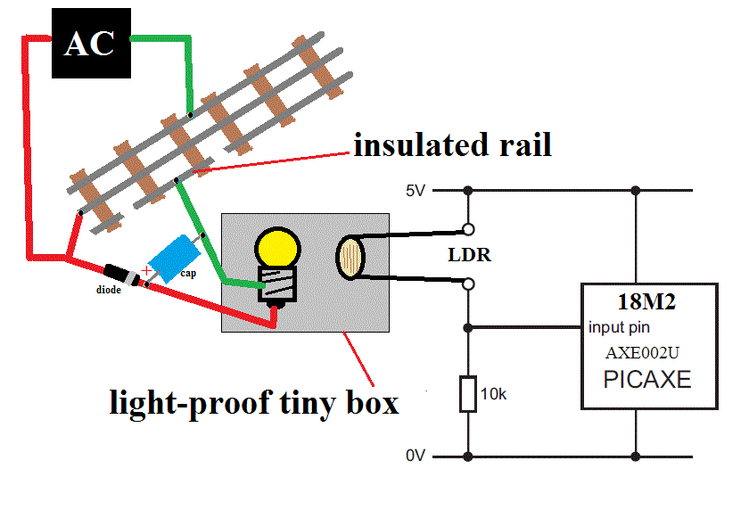
O.K. In an effort to share with like-minded hobbyists, this is my intention (I did almost the same thing with the old Timex/Sinclair 1000 and the Bite-Back I/0 board about 25 years ago).


This will be with a chopped wave AC controller, and it charges the cap to the full 18V even when the throttle is set to deliver what the locomotive will see as a variable voltage, and you get the 40% increase with the combination of the diode and cap. The controllers fixed voltage 77 watt wall wart is 18VAC. So the light should be a consistent brightness with little flicker. If it works like it did with the old Timex, I won't need the cap and diode.

I know there are optoisolators and LED options, but there are spikes that can be intense and I feel comfortable with this! Yes, it may be a Mickey Mouse circuit, but I always liked Mickey. ;)


A 3 rail metal wheelset (wheels -NOT-insulated from the axle) will ground the bulb. Simple for occupancy and triggers.

If for whatever reason it doesn't work, I'll go the READADC route.

Take care, Joe.
 
Last edited:

alhoop

Member
Somewhere in the documentation it is stated that a low is to be 0.2 times the supply voltage or less
and a high is to be 0.8 times the supply voltage or more not to exceed the supply voltage.
Shouldn't these figures be considered in the above calculations?

Regards
Al Hooper
 
Last edited:
Top