Remote for CD player

james1

New Member
Hi there,

I want to make a remote for my cd player.

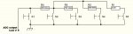
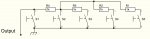
It has five buttons with resistors and one output (see attached).
(resistors not 1k)

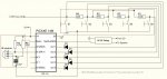
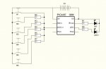
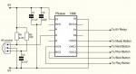
Could you please advise which chip to use and what would be the best way.

Thanks for your help.
 

Attachments

Last edited:

moxhamj

New Member
That is a very strange circuit. Is there a supply voltage anywhere? As it is it will present a varying resistive load between ground and the output depending on which button is pressed. Can you double check the circuit and put in the actual resistors?

The 14M is capable of doing this. It has a number of pins that can be configured as outputs or inputs and thus can simulate push button switches. The pins can be configured as an analog input to simulate the switch in an open circuit position, and can be configured as an output with a "low" to simulate the button being pushed and hence shorted to ground.

The details are in the appendix at the bottom of the first help file, but first can you double check the circuit.

Read through this thread http://www.picaxeforum.co.uk/showthread.php?t=8483&highlight=xbox&page=2 as this was a very similar project.
 
Last edited:

Technical

Technical Support
Staff member
You will probably find there is a pull up resistor to V+ within the actual CD player, so the circuit shown acts as a normal potential divider arrangement, each switch changing the value of the voltage seen on the connection labelled 'output' (actually goes to an ADC input on the CD player).
 

james1

New Member
Here is the proper circuit.

I was wanting to use the chip as you described and was just checking.

This is the first time I have seen this type of button configeration.
Will the 3.42V be enough for the chip and will transistors or just the pic pins be best for the buttons?
What circuit and code would be recomended for a IR remote?

Thanks
James
 

Attachments

Last edited:

moxhamj

New Member
Ah, that makes sense, and with Technical's suggestion and your measurement of a voltage it appears there is a resistor somewhere else. It shouldn't matter though as a 14M can easily simulate a button by switching between low and open circuit.

I'm pretty sure all the IR remote stuff is covered in the manual, including the relevant commands. Do you have access to the picaxe manuals? Essentially it is just a led and resistor for the transmitter, and a resistor and sensor at the receiving end. Look at the commands infrain2 and infraout in the second manual. The picaxe does all the clever work.
 
Last edited:

hippy

Ex-Staff (retired)
I've got a steering column CD control switch which works this way ( but no CD player for it ! ).

Looks like there are two choices for creating an IR remote for the CD player ( assuming that's what the question is ); use a PICAXE to read an IR remote and generate a pulse of right voltage for a period, or use the PICAXE to fake the button pushes of the circuit presented. The later would seem to be the easiest option.

A 14M and some diodes could perhaps pull each resistor down as required, otherwise it will be FET's or transistors across the switches.
 

james1

New Member
Thanks for your sugestions.

Here is my plan...

I will make an IR remote with a 08M on 3V. The button will be similar to the CD player as they will have resistors that is read by the ADC pin.
A 14M will receive the IR commands and make the corresponding pin low then high (like pushing the button).

Buttons:
Play
Stop
Previous
Next
Mode
Relay to 'mute' speakers

Do I and what type of resistors do I put on the serial pins?
What resistors should I use in the remote?

Attached are the circuit diagrams and below are the codes.


Code for remote:
Code:
main:
	let pins = %0000000
	input 3			'ADC input
	output 1			'LED	
	
	readadc 4,b1		'read ADC pin4 as b1
	if b1 = ## then main
	if b1 = ## then IR1	'mute
	if b1 = ## then IR2	'play
	if b1 = ## then IR3	'stop
	if b1 = ## then IR4	'previous
	if b1 = ## then IR5	'next
	if b1 = ## then IR6	'mode

IR1:
	high 1			'led on
	for b2 = 1 to 3		'send infrared code 3 times
	   infraout 1,b1
	   pause 45
	next b2	
	low 1				'led off		
	goto main
	
IR2:
	high 1			'led on
	for b2 = 1 to 3		'send infrared code 3 times
	   infraout 2,b1
	   pause 45
	next b2	
	low 1				'led off		
	goto main
	
IR3:
	high 1			'led on
	for b2 = 1 to 3		'send infrared code 3 times
	   infraout 3,b1
	   pause 45
	next b2	
	low 1				'led off		
	goto main
	
IR4:
	high 1			'led on
	for b2 = 1 to 3		'send infrared code 3 times
	   infraout 4,b1
	   pause 45
	next b2	
	low 1				'led off		
	goto main
	
IR5:
	high 1			'led on
	for b2 = 1 to 3		'send infrared code 3 times
	   infraout 5,b1
	   pause 45
	next b2	
	low 1				'led off		
	goto main
	
IR6:
	high 1			'led on
	for b2 = 1 to 3		'send infrared code 3 times
	   infraout 6,b1
	   pause 45
	next b2	
	low 1				'led off		
	goto main

Code for reciever:
Code:
'set symbols
	symbol mte = 0		'mute
	symbol ply = 1		'play
	symbol stp = 2		'stop
	symbol prv = 3		'prev
	symbol nxt = 4		'next
	symbol mde = 5		'mode
	

main:
	let pins = %00111111	'mute off, pins high
	infrain2
	if infra = 1 then mute1	'mute
	if infra = 2 then play1	'play
	if infra = 3 then stop1	'stop
	if infra = 4 then prev1	'prev
	if infra = 5 then next1	'next
	if infra = 6 then mode1	'mode
	goto main
	
mute1:
	toggle mte
	goto main

play1:
	low ply
	pause 100
	high ply
	goto main

stop1:
	low stp
	pause 100
	high stp
	goto main

prev1:
	low prv
	pause 100
	high prv
	goto main

next1:
	low nxt
	pause 100
	high nxt
	goto main

mode1:
	low mde
	pause 100
	high mde
	goto main

Thanks for all your help,
James
 

Attachments

Last edited:

moxhamj

New Member
I don't think the receiver will work as shown - the diode voltage drops are going to cause problems. Simulating a push button on a 14M is a bit more subtle - a button changes from a very high resistance to a short to ground. The picaxe can do this by simulating an unpushed button by making a pin an input (which sets it to a high resistance), or by making it an output and setting it low. The code is at http://drvernacula.topcities.com/controlling_devices_with_buttons.htm and it will only work for those 6 pins on a 14M as these are the only ones that can change from inputs to outputs.

Leave out the diodes. And on startup, the pins on the left of the 14M will default to high impedence but the three on the right will default to 'low' which for a button is 'on', so they will need to be set by the code as high impdence. Hopefully having three buttons pushed at once on startup won't upset the CD player.
 
Last edited:

james1

New Member
Thank you Dr_Acula for the info.

Attached is my new code and circuit.

I will order the bits in the next few days, so I there are any problems please let me know.

Current code for 14M reciever:
Code:
start:
	b0=0
	let dirsc=%00000000' poctc0-5 all open circuit
	symbol mte = 1	

main:
	infrain2
	if infra = 1 then mute1	'mute
	if infra = 2 then play1	'play
	if infra = 3 then stop1	'stop
	if infra = 4 then prev1	'prev
	if infra = 5 then next1	'next
	if infra = 6 then mode1	'mode
	goto main
	
mute1:
	toggle mte
	goto main

play1:
	b0=b0 or %00000001' leg10 as output (C0)
	let dirsc=b0
	low 3
	pause 500
	b0=b0 and %00111110' bit0 low
	let dirsc=b0
	goto main

stop1:
	b0=b0 or %00000010' leg9 as output (C1)
	let dirsc=b0
	low 4
	pause 500
	b0=b0 and %00111101
	let dirsc=b0
	goto main

prev1:
	b0=b0 or %00000100' leg8 as output (C2)    
	let dirsc=b0
	low 5' connect low
	pause 500
	b0=b0 and %00111011' preserve all bits and C2 low
	let dirsc=b0
	goto main

next1:
	b0=b0 or %00001000' leg7 as output (C3)
	let dirsc=b0
	low portc 3' connect low
	pause 500
	b0=b0 and %00110111' preserve all bits and C3 low
	let dirsc=b0
	goto main

mode1:
	b0=b0 or %00010000' leg 6 as output (C4=bit 4)
	let dirsc=b0
	low portc 4
	pause 500
	b0=b0 and %00101111' bit 4 low
	let dirsc=b0
	goto main
Thanks to all who helped.

James
 

Attachments

hippy

Ex-Staff (retired)
Breadboard it first. Try different options to see what does and doesn't work. I'd go with the diodes personally if I could get them to work. Adjusting the R's may overcome the voltage drop.

There's the potential problem that on turn-on the lows of the 14M ( with or without diodes ) could act as an unwanted button push, also without diodes, the three lines going high will pull-up the common line to +V which could cause problems.

Using transistors/FET's in parallel with the switches should overcome that, being able to handle the reset to 0V and open-collector.
 
Top