Really quick question.

Mumphry

New Member
Hey guys. Just a REALLY quick question. This is a circuit board I'm going to use as an input for a PICAXE. I'm making 12 of them so I have to get it right :p

The circuit design is someone elses, not mine so I don't know if my adaptation of diagram to circuit board layout will work.

So here's the question.
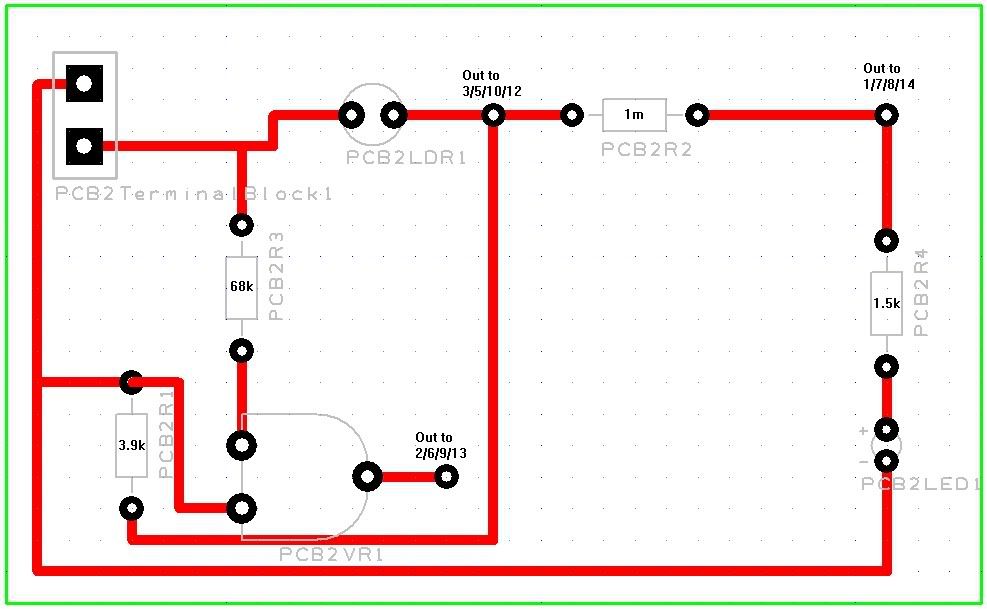
Does this diagram:


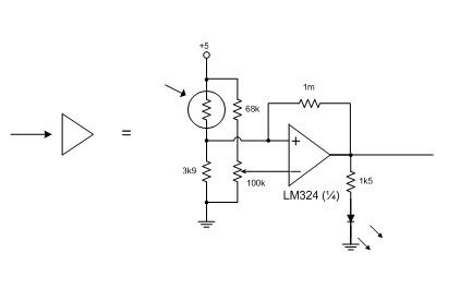
Match this circuit board layout?


It'd be good for just a quick yes or no or diagnosis of where I've gone wrong if I have.

Cheers.
 
Last edited:

manuka

Senior Member
Mmm - just what is the op amp application? I'd like to see the whole schematic & PCB, as it's more than a tad widely spaced IMHO. Has provision been made for mounting the entire LM324 DIP package (even though most of it is redundant)-you can't just slice off a ¼ of a IC of course! A batch of 12 really calls for YOU to FIRST breadboard evaluate the circuit, as someone elses quick lash up needs may not suit you own ( or vice versa).
 

Mumphry

New Member
oh, and where it says "out to w/x/y/z" the numbers there corresponds to a pin number on the LM324.

In other words, 4 of these circuits will be hooked up to one LM324.
 
Last edited:

hippy

Ex-Staff (retired)
When you say, "This is a circuit board I'm going to use as an input for a PIC", you should really say PICAXE if that is the case, PIC would logically be assumed to be a PICmicro.

Whether PICAXE or PICmicro can affect the effort people are willing to put in with helping with a queastion.
 

BeanieBots

Moderator
So it's an LDR light detector with a little bit of hysteresis and a variable switch point. That bit is simple enough to follow.
But WHY is the op-amp not on the board?
Why are there no 'proper' provisions to connect to the op-amp?
Taking a wire from a simple pad to another circuit (which I assume will be made/un-made frequently) will result in early failure of the pad.
Also, having break out points all over the place will lead to confusion.

Run all connections to one end of the board and fit a connector.

How far will these boards be from the Op-amp?
Long wires to op-amp inputs, not a good idea!

Use sensible labels for the break out points not pin numbers.
Eg Suppy/Vcc, 0v, +Ve IP, -Ve IP etc.

EDIT:
Also, your resistor labels are confusing.
eg you have a 1k5 labelled as PCB2R4.
Somebody might think that should have a 2R4 resistor fitted there.

Remember, this is going to be used by somebody else.
Such a simple circuit should have ZERO ambiguity on ANY aspect.
 
Last edited:

manuka

Senior Member
Application? End use? Power supply issues? Although the LM324 (along with the 741) is a classic reliable op. amp, it's decades old & dates from back in the PC 286/386 era! Current drain considerations alone may justify a modern more efficient type.
 

Attachments

Mumphry

New Member
The op amp isn't on the board just for simplicity. It's easier to produce 12 separate identical board than to make 4 separate boards. The Op-Amp is no more than 5 cms away from each of the boards. Once the boards are connected to the Op-Amp I don't plan on disconnecting them frequently, only for fault diagnosis.
 

BeanieBots

Moderator
Stan, how could you? The LM324 is a 'classic'.
Sure it's been around for years but it's a good all rounder and VERY stable.
OK, it pulls over 1mA quiescent but many of the 'modern' op-amps don't have anything like it's rail-to-rail capabilities and many will oscillate if not treated with a little respect.
 

BeanieBots

Moderator
@Mumphry,
5cm should be OK.
No mounting holes?
Wires from the middle of a board is well.... just YUK.
Take all the connections to one edge even if you don't use a connector.
At least provide some means of securing the board.
Consider 741 on each board. (another 'classic' op-amp)
 

hippy

Ex-Staff (retired)
With respect to the original question, does the board match the circuit ... assuming you've got the connections for the LM324 right ( I didn't check ) it looks okay to me.
 

Mumphry

New Member
Nah, no mounting holes. Just going to slide into a small slot type thing. Sorry, hard to explain :p

Cheers hippy.

And beaniebot? I'll move all the connectors to the side of the board. It'd make things a lot easier when it comes to connecting as well considering my board layouts.

Thanks everyone for the quick responses. I can start etching tomorrow now :p
 

westaust55

Moderator
Okay there is an LDR used to detect light level and a signal into a PICAXE.

What is the real reason for the Op-Amp that the PICAXE cannot achieve with READADC and some code to determine the level and hysterisis?

You are using an input either way so unless therre are many analogue inputs and you are restricted to an high/low (on/off) input keep it simple and program code can be more flexible.

I have LDR's (from Jaycar) the when used with a 2.2kOhm resistor gives virtually the full range for READADC (from around 0 or 1 up to !~250 under torch light and up to 254 or 255 in Perth WA sunlight).
 

moxhamj

New Member
Yes, further to westy's point, is this *really* going to a picaxe?

The 324 is one of my favourite chips but for sensing light, the picaxe is so much easier. Just one LDR and one resistor. Then do it all in software. And you can read more than one LDR into a picaxe too. Why add the unnecessary board space and components?

In fact, a 324 circuit will be worse because it can't quite swing rail to rail. More likely only 1.5V to 3.5V. So you lose more than half the resolution. With a picaxe you go all the way from 0V to 5V.
 
Last edited:

boriz

Senior Member
Looks like this could be hugely simplified using a 4-to-16 multiplexer (of which you only use 12) to select each LDR in turn, reading them all with a single ADC Picaxe input. Any threshold adjustments can be either set in the software (once calibrated) or adjustable using a single pot read by the Picaxe. It can all be done on one small board.
 
Top