Hi,
READINTERNALTEMP is a rarely-used command, probably because it's basically [contentious view] "useless" [/contentious view]. To qualify that slightly, it's useless unless you have a regulated power supply (which the vast majority of PICaxe projects don't have) and aren't interested in negative temperatures and/or an easy calibration procedure. Also, the related Microchip Application Note AN1333 is now quite old.
I've written several posts and code snippetts on the topic, which I won't go into detail here, but a brief summary is that a stable (or measured) supply voltage is absolutely essential to produce useful results. Also there was/is a bug in PE5 that produces erroneous results; the "fix" in PE6 increases code-size considerably, and still doesn't accommodate negatve (degrees C) temperatures, nor any better calibration strategy than "change K and see what happens".
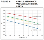
Just a little more background: A "rule of thumb" is that the forward voltage of a silicon diode normally drops by about 2.0 mV per degree C rise in temperature (perhaps 1.75 at lower currents), but the Microchip PIC data sheet specifies only 1.32 mV/C. Furthermore, if you use the FVR as a reference voltage to measure the supply rail, then that itself has a temperature coefficient, which reduces the effective tempco to just 1.24 - 1.25 mV/degree C.
On that basis, I have produced some very satisfactory code (IMHO) which can measure "chiptemp" to within just a few degrees. Since I don't have an environmental test chamber ( ) my calibration method was to "stuff it in the freezer for an hour", which gives a useful temperature change (> 40 degrees) from room temperature (and I do have a freezer thermometer). But I still had niggling doubts about that -1.25 mV/C.
So now to the point of this thread. I was recently browsing Microchip's website and they now have a new AN2092: "Using the Temperature Indicator Module" (dated 2016). I had to smile at the comment on page 2 that:
, but the AN does contain much better detail than AN1333. However, on pages 4 and 6 there are two rather contradictory statements :
So it appears that for my "freezer" test I need to include another correction factor of about 2 - 4 degrees! I won't be near my "hardware" for a few days, but maybe I'm finally close to getting "usable" temperature results from the PIC{axe} chips.
EDIT: See update in Post # 8.
Cheers, Alan.
READINTERNALTEMP is a rarely-used command, probably because it's basically [contentious view] "useless" [/contentious view]. To qualify that slightly, it's useless unless you have a regulated power supply (which the vast majority of PICaxe projects don't have) and aren't interested in negative temperatures and/or an easy calibration procedure. Also, the related Microchip Application Note AN1333 is now quite old.
I've written several posts and code snippetts on the topic, which I won't go into detail here, but a brief summary is that a stable (or measured) supply voltage is absolutely essential to produce useful results. Also there was/is a bug in PE5 that produces erroneous results; the "fix" in PE6 increases code-size considerably, and still doesn't accommodate negatve (degrees C) temperatures, nor any better calibration strategy than "change K and see what happens".
Just a little more background: A "rule of thumb" is that the forward voltage of a silicon diode normally drops by about 2.0 mV per degree C rise in temperature (perhaps 1.75 at lower currents), but the Microchip PIC data sheet specifies only 1.32 mV/C. Furthermore, if you use the FVR as a reference voltage to measure the supply rail, then that itself has a temperature coefficient, which reduces the effective tempco to just 1.24 - 1.25 mV/degree C.
On that basis, I have produced some very satisfactory code (IMHO) which can measure "chiptemp" to within just a few degrees. Since I don't have an environmental test chamber (
) my calibration method was to "stuff it in the freezer for an hour", which gives a useful temperature change (> 40 degrees) from room temperature (and I do have a freezer thermometer). But I still had niggling doubts about that -1.25 mV/C.So now to the point of this thread. I was recently browsing Microchip's website and they now have a new AN2092: "Using the Temperature Indicator Module" (dated 2016). I had to smile at the comment on page 2 that:
Well yes, so will "guessing" it to be +40 degrees"Generally this equation will produce an uncalibrated temperature value that is within 100°C of the actual temperature."
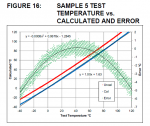
, but the AN does contain much better detail than AN1333. However, on pages 4 and 6 there are two rather contradictory statements :Here is one of those graphs:"The graphs show that the temperature response is very linear when verified at 10° intervals."
"The graph looks reasonable when first viewed but much of the measurement error is lost in the scale of the graph. A better option is to look as a scatter diagram of the error of the individual data points".
So it appears that for my "freezer" test I need to include another correction factor of about 2 - 4 degrees! I won't be near my "hardware" for a few days, but maybe I'm finally close to getting "usable" temperature results from the PIC{axe} chips.
EDIT: See update in Post # 8.
Cheers, Alan.
Last edited: