Hi,
I would also put a capacitor directly across the motor output, unless I could check (with an oscilloscope or maybe capacitor-coupled ac multimeter) that the "dc" is reasonably "clean".
I doubt if that circuit will read accurately above about 6 - 8 volts because of leakage through the zener. I posted the zener curves up to 4V3 a few days ago in
#9 here and a 4V7 is similar. Your 22k resistor will only deliver about 400uA (from 12 volts) so you need the zener leakage to be below (say) 10
uA (or far lower if you want accuracy equivalent to 10 bits A/D) which is impossible to predict from those curves (the first calibration line is at 10
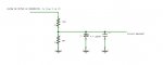
mA. With the values shown, power dissipation ratings would be neglibile.
My design would assume a maximum voltage on the PICaxe pin of say 2.0 volts, thus 10 volts across the upper resistor, dissipating say 100mW (comfortable for a typical "1/4 watt" type), making it 1k ohms (P = V*V/R). Thus the lower resistor could be 200 ohms. On many PICaxes you can use an internal 2.0 volt reference voltage for the A/D converter, but IMHO there are many other factors you need to consider before getting an accuracy that justifies using 10 rather than 8 bits.
You may want to measure the "loaded" voltage as well, which would need a load resistor rated to however much power you're hoping to generate from the motor.
EDIT: If the PICaxe has a 5 volt regulated supply, then perhaps the best way to use the zener is to run it nearer its "nominal" current (5mA) with a resistor to the supply rail, perhaps 100 ohms would be about right. Then clamp any excessive input pin voltage to this via a small silicon diode (anode to divider resistors, cathode to the zener diode). This should prevent any overvoltage being "dumped" into the supply rail but not affect the accuracy of the divider chain below about 5 volts on the input pin.
If you only intend to make one (or an occasional) measurement with the PICaxe then you probably need a large filtering capacitor, perhaps hundreds of uF, but maybe less with the resistor values you originally suggested. However, as the "dc" voltage waveform (ripple) is unknown (unless you have a 'scope) then this is a good opportunity to analyse the waveform characteristics. Use a fairly small capacitor (perhaps 10 - 100nF) and make multiple A/D measurements in a loop (e.g. FOR b1 = 0 TO 255 : ....) and calculate Average, Maximum and Minimum voltages. If you're more ambitious you might even calculate the RMS voltage and/or the ripple frequency.
Cheers, Alan.