Readadc values

sid

Senior Member
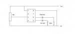
Because I seem to be getting odd readadc values I put together a simple circuit with a 10k pot going into input 4 and a couple of leds coming out of outputs 1 and 2 and used the simple code
Code:
output 1
output 2
main:
readadc 4,b0
if b0< 1 then red
if b0> 100 then yellow
pins=0

red:
high 1
low 2
goto main

yellow:
high 2
low 1
goto main
The pot with a voltmeter across it covers the complete range of 4.63-0v
however the point at which the red led switchs off and the yellow led switchs on is 1.84v.
As I understand it the readadc value is proportional to the voltage, so the higher the voltage - the higher the readadc value.
I'm just puzzeled by why the readadc value appears not to be proportional to the voltage scale of the pot. Please could someone advise me.
 
Last edited:

BeanieBots

Moderator
Is your POT linear?
Many POTs, particularly ones used for "volume control" are logrithmic.

EDIT:
The theoretical value for your code would be 1.81 anyway, so not very far out!
PPS. Edit crossed with eclectic's post
 
Last edited:

George Sephton

Senior Member
It's proportional to the voltage supplied by the PICAXE, ie a 10K pot between 0 and 10V connected to a 5V powered PICAXE will produce 255 from 5V onwards, leaving half of your pot useless.
 

sid

Senior Member
It's proportional to the voltage supplied by the PICAXE, ie a 10K pot between 0 and 10V connected to a 5V powered PICAXE will produce 255 from 5V onwards, leaving half of your pot useless.
Hi George, the pot is connected to the same 5v supply as the picaxe not a 10v supply:confused:
 

sid

Senior Member
Is your POT linear?
Many POTs, particularly ones used for "volume control" are logrithmic.

EDIT:
The theoretical value for your code would be 1.81 anyway, so not very far out!
PPS. Edit crossed with eclectic's post
Thanks, because of Georges post I tried using both a 4k7 linear and logrithmic pot with exactly the same result the leds change over at 1.83v.
Whats the difference between log & lin ?
I still don't quite get why half the pot provides no reading and would be greatful if someone could explain in simple terms,
thanks,Sid
 

sid

Senior Member
Has eclectic's and BB's reply answered your question?
I'm afraid not as I don't understand the answers given,
e's answer states 4.63/255*100=1.83 ??? what does that mean exactly
I've read the manual which states that in low resolution only an input between 0-3.3v will be read, so I'm assuming that 1.83 is the top part of the votage range that can't be read ?
I tried changing the readadc to a readadc10 as the manual states that the complete voltage range can be read, with this I find that the leds just alternate between red & yellow as I turn the pot when the red led should come on close to one end of the turn ,there should then be a null point where no leds are lite and then the yellow led should come on for the rest of the pots turn.
I'm just trying to understand why the the position of the pot "appears" to bare little relation to the readadc value, or at least does not work in the logical way that I can understand. Please could any answers be really simple, assume that I know nothing , rgds, Sid
 

Dippy

Moderator
Are you reading the bit about 'low resolution'?
If so, that referred to the ancient 08 and 18 PICAXEs.
Read the Manual.

Which PICAXE have you got?

OK, briefly:
The PICAXE Vsupply is the reference. Say, for arguments sake, 5V.
The ReadADC is 8 bit. 255 steps.
So, 255 = 5V.
So each 'step' is 5/255 Volts.

In your case, you said "the complete range" is 4.63 volts.
This implies that the Vsupply to PICAXE is also 4.63 volts.
So, in your case, each 'step' is 4.63/255 Volts
You, in your code had 100 as a threshold.
So, 100 steps is 100 x 4.63 / 255 = ? (You can do this bit).

Its simple ratios.
If you choose ReadADC10 (10 bits) then you will need a word variable as 10 bits means a maximum number of ? (You can do this bit too).

Again simple ratios.
Simple algebra.


Note: there will be some error in the system, just like your $2 multimeter. So don't expect accuracy to umpteen decimal places ;)
 
Last edited:

boriz

Senior Member
A LINear pot has a track with a constant fixed resistance for each mm of its travel.

A LOGarithmic pot has as track where each mm has a slightly different resistance than the mm next to it (increasing towards one end). When the wiper’s in the middle, there is NOT an equal resistance on either side. Far from it. In fact to get equal resistance above and below the wiper, the wiper needs to be maybe only 1/10th of the full travel away from the low-resistance end. They are designed for Audio applications mainly.

See: http://en.wikipedia.org/wiki/Logarithmic_scale

You definitely need to know what type you are using. They both look identical, though they are usually marked LIN or LOG. If not marked one way or the other, use a multimeter to check it.
 

Dippy

Moderator
Ah yes, good point. Is he referring to confusion re voltage at ADC or the position of his knob.
BB mentioned log pots earlier.
If its a log pot then he can sandpaper a bit off the track.

Only sid can tell us what it is he's referring to.
Over to you sid....
 

BeanieBots

Moderator
I'm afraid not as I don't understand the answers given,
e's answer states 4.63/255*100=1.83 ??? what does that mean exactly
I've read the manual which states that in low resolution only an input between 0-3.3v will be read, so I'm assuming that 1.83 is the top part of the votage range that can't be read ?
I tried changing the readadc to a readadc10 as the manual states that the complete voltage range can be read, with this I find that the leds just alternate between red & yellow as I turn the pot when the red led should come on close to one end of the turn ,there should then be a null point where no leds are lite and then the yellow led should come on for the rest of the pots turn.
I'm just trying to understand why the the position of the pot "appears" to bare little relation to the readadc value, or at least does not work in the logical way that I can understand. Please could any answers be really simple, assume that I know nothing , rgds, Sid

You've miss read slightly.
The "low resolution" you refer to is talking about the VERY low resolution of the 08, not the 8bit/10bit resolution of the 08M (and others).

The input range is the FULL voltage range of whatever voltage powers your PICAXE.
The equation given shows what voltage is expected to trip your code.
I think your code is also not quite doing what you think it should.

ReadADC will break down your voltage (4.63v) into 256 sections.
Your code triggers at the 100'th division. (4.63v/256 * 100 = 1.81v)

Replace your code with this to see what is going on.

Main:
ReadADC 1,b0
debug
goto main.

Then move your POT and see how the position of your POT and the value of b0 relate to each other.
If your POT is linear, you should get a value of 128 when it is in the middle.
If it is a log pot, most of the change will be scrunched up at one end.
 

sid

Senior Member
Ah yes, good point. Is he referring to confusion re voltage at ADC or the position of his knob.
BB mentioned log pots earlier.
If its a log pot then he can sandpaper a bit off the track.

Only sid can tell us what it is he's referring to.
Over to you sid....
Thank you all, that does seem to make sense,
I was using a readadc10 comand but trying to put the value into a b0 container rather than a w0 one, this mistake has lead to understanding.

The bit that really gets me is that even if I change the threshold from 100 to 1 how far the knob has to travel to reach this threshold, it just seems disprotionate to the volage range but I guess that must be down to the limitations of the pot.
Thanks all for the maths lesson
Rgds, sid
 

Attachments

BeanieBots

Moderator
The value of 100 for readadc should be replaced with 400 to give the same position when using ReadADC10. Also, as you've found out, a word is required for 10-bit values.
 
Top