....but it works of the sensor is exposed to quickly changing light levels....On the contrary. I'd say that suggests hardware working OK and a software error! I'll try to spend some time looking at your code but probably not soon.
readadc or readadc10
- Thread starter davidwf
- Start date
BeanieBots
Moderator
My point exactly. (short of going through your code).
I can not think of any hardware issue that could cause that effect. (assuming you still have R4=10K).
Actually, when at 1M, the LDR may well be significantly effected by temperature.
Got a datasheet??
I can not think of any hardware issue that could cause that effect. (assuming you still have R4=10K).
Actually, when at 1M, the LDR may well be significantly effected by temperature.
Got a datasheet??
Last edited:
Re post #26: "After chewing over the theory, deliberating, and having friendly banter here, there often isn't much time left to actually do anything"
I like that. The people who build steam engines for a hobby have a delightful term for theorists. They call them a "Professor Pink Hands"
With all this talk of source impedences, why not just use your LDR with whatever resistance works, and run it through a CA3140 configured as a voltage follower? Ie input to +, and output to -ve. You already have one in the circuit anyway. Then there are no issues with the strange effects from the characteristics of the the picaxe ADC.
Last edited:
sort of defeats the object of using the PIC.... ?...no.....?Re post #26:
.........why not just use your LDR with whatever resistance works, and run it through a CA3140 configured as a voltage follower?
Last edited:
er, no, smacked wrists !.......still a bit rusty on what & where to enter to check this type of thingI take it you haven't done any debug/sertxd 'test prints' in situ to check the route your code takes?
It may help.
Davidwf - Testing the ADC input every 5 mins? Of course. That probably is the answer!!
The higher you make the series resistance (and hence the darker the light level you are measuring), the slower the LDR responds. So you need to increase the delay correspondingly.
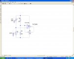
And you can probably do away with the need for a CA3140 voltage follower. Put the LDR in series with a big resistor, and put a big low leakage cap between the adc input pin and ground. Then the cap supplies the energy to keep the adc input constant while it is being read. It would need to be low leakage - eg a 100uF tantalum. 22uF would probably work though.
The higher you make the series resistance (and hence the darker the light level you are measuring), the slower the LDR responds. So you need to increase the delay correspondingly.
And you can probably do away with the need for a CA3140 voltage follower. Put the LDR in series with a big resistor, and put a big low leakage cap between the adc input pin and ground. Then the cap supplies the energy to keep the adc input constant while it is being read. It would need to be low leakage - eg a 100uF tantalum. 22uF would probably work though.
Last edited:
Grant Fleming
Senior Member
David,..... remind me if you will where this lives...I have seen it but cannot find it !
Thanks
The 'enhanced download circuit' is in BASIC Commands section/readadc10 - page 122, (Schottky diode).
Grant
Nope, didn't make any difference, neither did adding a 0.1uF capacitor ....back to the drawing board I guess....Davidwf - Testing the ADC input every 5 mins? Of course. That probably is the answer!!
For test 'prints' just put a Sertxd statement in at the start of each subroutine. An example I gave previously.
Connect your device to PC, run up the comms window and let the code run.
THEN you can see where it's jumping. Easy. Though don't put Sertxd in a fast time-critical loop becasue of the delay it introduces whilst sending the serial out. Obvious I know but regularly forgotten/not considered.
For twilight switching I ended up using a TAOS TSL250R I think (I can't find the circuit).
http://uk.farnell.com/1182346/optoelectronics/product.us0?sku=taos-tsl250r-lf&_requestid=75605
This component comes in different varieties. Check them out if bothered.
The LDR resistance at low light levels was just too high for meaningful/reliable ADCing.
Far better results with TAOS and, as far as code is concerned, a very quick swap out.
Light-F devices are also available.
(For battery stuff the current consumption is a consideration but this can be got-around with sensible switching i.e. a transistor.)
I was using that device in an outdoor dawn-to-dusk people counter. Can't remember exact lux levels, got a feeling it was about 10 to 30 lux, so fairly dim (yes, go on, you want to say it!). It was one of my first PICAXE projects and had a similar problem to yours.
They won't explode if exposed to daylight - if that's what you are asking.
However, their dynamic range is more limited than an LDR. So, if exposed 'nude' to daylight, they couldn't distinguish between bright and very bright, without a tinted filter to offset their oerational range. But for dark - to- not-so-dark they should be fine.
There are several versions so you may like to check them out. Have a search on Farnell for example. There are also light-frequency too.
BeanieBots
Moderator
Before you commit to buying a different sensor, have you actually tried changing R4 to say 47k and putting 100nF on the ADC input?
BeanieBots
Moderator
I assumed that refered to the update rate and cap. Neither of which I'd expect to have any effect on a 10k//LDR impedance. The only way to increase the returned value (higher sensitivity in lower light level region) is to increase R4 or use a different sensor. Most people have an assortment of resistors to hand. Got to be worth trying first.
Yes I have....but it didn't make any difference at all - apart from altering the trigger threshold of courseBefore you commit to buying a different sensor, have you actually tried changing R4 to say 47k and putting 100nF on the ADC input?
I can't understand why, if I am sampling it (say) every 5 mins it doesn't trigger.....
....I put the capacitor between adc pin and 0V....correct ????..
I will try the op-amp as suggested earlier (#44) at least it will prove if the source impedance is the problem
..sorry about the delay in replying - had to do some work !
Last edited:
BeanieBots
Moderator
If the changes you have already made didn't fix it, I don't think an op-amp will have any effect either. If you have the parts to hand, then do try it but IMHO, you should now concentrate on the code.
Can you pls restate the problem. On the first post you said
"For an external light controller I am trying to read the light level using an LDR connected to pin 1 of a PICAXE 18X (I need extra in / out so the 18X is required) and 0 to 255 is not giving me enough range - the required levels are around 10 to 20."
A value of 0 corresponds to 0V. And a value of 255 corresponds to 5V. So that is the full range of the power supply, and it is not possible to go any higher than 5V nor lower than 0V.
I do not understand what you mean by 10-20. That falls within the range 0-255.
Are you talking about voltage range or resolution here?
Maybe you could just go back to basics and talk about volts. If you put an LDR in series with a resistor and measure the point at which they join, the volts will vary. But you will find that the resistance of an LDR varies a lot - megohms in dark and only a few ohms in sunlight. And the value does not change like you think it does, as the eye perceives light in a logarithmic way. And different LDRs behave differently.
Very simple test. Can you take an LDR, not connected to any circuit, and measure the resistance. Measure it in the light. Measure it in the dark. And measure it at the light levels you want to test - eg dusk. If you can post those values, we can work out a suitable circuit and what sort of resistor it needs and whether an op amp is needed or not.
Addit - on the original circuit no reset circuit is shown. It could also be randomly resetting if that pin is floating.
Last edited:
On the bench it functions correctly - i.e. with rapidly changing light levels it switches OK, in situ with slowly changing levels it does not switch at all.Can you pls restate the problem.
These are the levels returned by debug - with readadc10 they are now around 200 at the required switch on and 400 at the required switch off light levels....BUT I have noticed that under a constant light level they very considerably, e.g. up to 300+ and down to 100the required levels are around 10 to 20
I have checked the supply voltage at the PIC and it is 4.915V not varying at all - not even by 1mV, (I am fortunate enough to own a logging multimeter with a fast min/max function)
.......with a constant light level, the voltage is constant as you would expect but the ADC is changing a LOT (as above)If you put an LDR in series with a resistor and measure the point at which they join
In light = 50 ohms, in dark >2meg ohm, at the required trigger level approx 80K ohmCan you take an LDR, not connected to any circuit, and measure the resistance
No it is terminated with a 1K to +5V, I just showed the relevant parts of the cct......on the original circuit no reset circuit is shown. It could also be randomly resetting if that pin is floating.
....update.....
I tried with a CA3140E as suggested in #44 and the behaviour was no different - i.e. still not switching correctly......
I now feel that the problem is being caused because the output from the ADC is varying by so much....I am using a USB connection and a laptop running on batteries so I don't think I need the enhanced download cct mentioned in #34
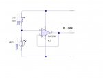
Ultimately I could use an op-amp to do the switching which was how my old cct worked - albeit with a bucketful of other components as well - cct diagram attached - to present the PIC with a simple on / off input but this sort of defeats the object of using it in the first place - I wanted to be able to select the switching point in software
Thanks for all your suggestions, any final ideas before I go (partly back) down the analogue route....
Attachments
-
 82.1 KB Views: 15
Last edited:
BeanieBots
Moderator
If you've buffered the signal and the reading still fluctuates, then your analogue circuit won't work either.
You've either got a circuit fault or a code error.
Get a 10k pot and put it on your ADC input. Does that give you a stable reading?
You've either got a circuit fault or a code error.
Get a 10k pot and put it on your ADC input. Does that give you a stable reading?
Get back to basics and just write a few lines to read the ADC and experiment with things. Try a pot AS SAID BY BB (perfectly visible and we have all read it ") ) and then your LDR circuit and then a buffered LDR circuit. You've got something wrong somewhere.
) and then your LDR circuit and then a buffered LDR circuit. You've got something wrong somewhere.
I wouldn't have been surprised by fluctuating numbers from an LDR as a high impedance source - I got similar behaviour when i tried it before. But with an op amp buffer? That sounds odd assuming your op-amp circuit is OK of course.
) and then your LDR circuit and then a buffered LDR circuit. You've got something wrong somewhere. I wouldn't have been surprised by fluctuating numbers from an LDR as a high impedance source - I got similar behaviour when i tried it before. But with an op amp buffer? That sounds odd assuming your op-amp circuit is OK of course.
Yes it did, absolutely stable....so with a bit more experimenting I found that a 100uF cap across the LDR (i.e. +5v to ADC input pin) also gave a dead stable reading - 10uF, 47uF weren't enough .....I then increased the source resistor to 82K (actually it was OK up to 220K but the LDR is about 80K at the required light level) and the ADC value is around 500 which gives a bit more scope for adjustment.Get a 10k pot and put it on your ADC input. Does that give you a stable reading?
Tomorrow will tell if it is going to work !
Yes, the op amp cct. seems to be OK - with a pot replacing the LDR it tracks the input voltage as it should....Get back to basics and just write a few lines to read the ADC and experiment with things. Try a pot AS SAID BY BB (perfectly visible and we have all read it
I wouldn't have been surprised by fluctuating numbers from an LDR as a high impedance source - I got similar behaviour when i tried it before. But with an op amp buffer? That sounds odd assuming your op-amp circuit is OK of course.
....as per my reply to BB I found that a 100uF cap across the LDR seemed to be the answer - EVEN WITH the buffered circuit (!)....don't ask me why, I have only been a hobbyist for 40 years
!!!I think you were meant to put the cap between ADC & Gnd/0V. It then acts as a reservoir to dump into the ADC tiddly cap.
But an explanation of this is tricky as I don't know the ins & outs of the READADC firmware. And that makes a difference with respect to the ADC cap charging times.
Shouldn't be necessary at all with op-amp buffering, but then I don't know how you wired your op-amp. Odd.
But if it works, then just put the lid on.... and sit back.
"I have only been a hobbyist for 40 years" - but what at ?
My hobby of flower arranging hasn't helped my electronics at all.
But an explanation of this is tricky as I don't know the ins & outs of the READADC firmware. And that makes a difference with respect to the ADC cap charging times.
Shouldn't be necessary at all with op-amp buffering, but then I don't know how you wired your op-amp. Odd.
But if it works, then just put the lid on.... and sit back.
"I have only been a hobbyist for 40 years" - but what at
?My hobby of flower arranging hasn't helped my electronics at all.
BeanieBots
Moderator
"I found that a 100uF cap across the LDR (i.e. +5v to ADC input pin) also gave a dead stable reading "
Have I got this right, you put the cap between 5v and the ADC input?
It should go between 0v and the input. Connecting to 5v will reflect any supply fluctuations straight into the ADC
The rest doesn't quite add up. If the LDR is 80k at the required level and your tests were OK up 220k using a resistor, then that confirms that the underlying issue is NOT impedance related.
Some fluctuation (as stated by Dippy) is to be expected, so again, this points to how your code copes with such a scenario.
Putting 100uF on the ADC input is a MASSIVE slug. Only 100nF is required to resolve the ADC load problem. Again suggesting that the code "gets it wrong" when the input changes direction.
Another thought. In your "real" setup, have you put the LDR out on a long lead from the PICAXE? If yes, then it should be coax cable. Better still, put an op-amp buffer up at the LDR end, not the PICAXE end.
I agree it shouldn't be required but......I think you were meant to put the cap between ADC & Gnd/0V. It then acts as a reservoir to dump into the ADC tiddly cap.
But an explanation of this is tricky as I don't know the ins & outs of the READADC firmware. And that makes a difference with respect to the ADC cap charging times.
Shouldn't be necessary at all with op-amp buffering, but then I don't know how you wired your op-amp. Odd.
cct diagram for the voltage follower attached
Attachments
-
 16.1 KB Views: 19
BeanieBots
Moderator
Ah, that's why you needed 100uF to have any effect.
The voltage follower is a low impedance. That's the idea behind it.
(a cap on the output of some op-amps can actually CAUSE oscillation).
The cap should go across the LDR.
Sorry Dippy, the echo was because I actually started my reply before yours but got distracted half way through.
The voltage follower is a low impedance. That's the idea behind it.
(a cap on the output of some op-amps can actually CAUSE oscillation).
The cap should go across the LDR.
Sorry Dippy, the echo was because I actually started my reply before yours but got distracted half way through.
Yes that's right - ACROSS the LDR, haven't tried it LDR to 0V - too late to try it tonight, maybe tomorrow, curtain motor might wake the Mrs !!!Have I got this right, you put the cap between 5v and the ADC input?
Agree but like I said, the supply voltage is rock steadyIt should go between 0v and the input. Connecting to 5v will reflect any supply fluctuations straight into the ADC
- which is what we suspected originallyIf the LDR is 80k at the required level and your tests were OK up 220k using a resistor, then that confirms that the underlying issue is NOT impedance related.
Yes but it only takes about 5 seconds to settle - no problem with that, and the reading remains rock solid after settlingPutting 100uF on the ADC input is a MASSIVE slug
It is about 2 feet - same as "on the bench", I agree with your thoughts but even with it directly onto the input terminals it made no difference.In your "real" setup, have you put the LDR out on a long lead from the PICAXE?
Sometimes theory just doesn't add up does it ....
Last edited:
Dumb question - but I still don't understand the problem.
You said "On the bench it functions correctly - i.e. with rapidly changing light levels it switches OK, in situ with slowly changing levels it does not switch at all."
It doesn't switch. Ie - is it reading the correct value but not turning something on?
Ok, you have a box/PCB etc and it is not doing what it is supposed to do. It seems you need to break down the problem into parts. What values, for instance, are in the picaxe registers at the point it is supposed to switch but doesn't.
If you don't know, use some debug statements.
I'm still not even sure if this is a hardware problem or software problem.
correct...when the level falls below 500 it should - after a delay of 20 mins - turn the lights on [lines 75 to 86] (o/p 7) and close the curtains (o/p 1), likewise when it rises above 700 the curtains should open [lines 108 to 124] listing attachedYou said "On the bench it functions correctly - i.e. with rapidly changing light levels it switches OK, in situ with slowly changing levels it does not switch at all."
It doesn't switch. Ie - is it reading the correct value but not turning something on? .
Debug reports the correct ADC value (attached)
Still doesn't work but at least the ADC reading is now stable
Attachments
-
7.5 KB Views: 7
-
208 bytes Views: 6
Last edited:
Er, no....smacked wrists....I still can't quite get my head around that procedure - sorry...perhaps an example or 2 ?Still haven't tried little Sertxd messages at the start of each subroutine?
So you can follow your code on the Terminal screen?
How do you know what your code is doing?
BeanieBots
Moderator
Manual 2, page 146.
Just put the command in a few strategic places in your code.
You can then know WHERE you are in the program and WHAT VALUE various variables are at that time.
I've just had a QUICK look at your code. One thing which concerns me is what happens when it is seen as dark and then goes light again before 1 minute has elapsed. From what I can make out (and I may be wrong) it can get stuck in a loop.
I don't have the time or patience to map it all out in a flow diagram but I think you should. There is very strong evidence that this is a coding issue.
What happens in the transition from each of your test routines if the value changes enough (in either direction) to set a different test point?
Does your code make any assumptions about the direction of change? I think it does. Again, I might be wrong but hopefully somebody else will go through it more thoroughly than I have and confirm one way or the other.
......it SHOULD (I think) be trapped by the "still dark" / "final dark" & "still light" / "final light" functions that I added just for that purpose........ One thing which concerns me is what happens when it is seen as dark and then goes light again before 1 minute has elapsed. ....
Thanks for the link, I WILL have a look and try to understand it.....I will try !
"It SHOULD (I think)...."
Are you sure? No?
Well, stop thinking and put 'Sertxd's in your routines and plug in your PC
I'm sure I've said this before on this thread. Honest, when things get too much and the brain is on fire it can really help.
Something like, for xample, in your StillDark routine:-
sertxd(“Still Dark Routine. The value of LDR is ”,#w1,13,10)
is it w1 I can't remember??
similar ditto for other routines. Then you can follow the progress of your code on your terminal screen.
Not difficult eh? And it may (MAY) save another 8 pages of thread too... may....
BeanieBots
Moderator
In the mean time, here's how I'd do it.
Everyone has there own method but as a rule, I try to keep all sensor inputs in one area and avoid long pauses.
main:
Read in your buttons and ADC.
If buttons pressed go do whatever.
ReadADC LDR
If LDR not dark or light, then let Counter=32768 'Mid point of a word.
If LDR >= Dark then Counter=Counter-1 min 2' stop underflow
If LDR <= Light then Counter=Counter+1 max 65534 'stop overflow
If Counter>52768 then it's been dark for pause*20000 mS
If Counter<12768 then it's been light for pause*20000 mS
pause 60 'For 20 minutes delay
Goto main
The simple loop either resets a counter (level), increments it or decrements it depending on the light level. Only ONE readADC line to avoid any complication with changing levels between readings and the PICAXE only sits doing nothing for pause 60. The rest of the time it is checking the light level and your buttons.
Last edited:
I just noticed.
In your 'dark:' routine and others you're doing a readadc not readadc10. I guess that doesn't help...
...that would have shown up with test prints of course...
If you put the READADC10 in a subroutine then you wouldn't have to go through changing everything and missing some things.
In your 'dark:' routine and others you're doing a readadc not readadc10. I guess that doesn't help...
...that would have shown up with test prints of course...
If you put the READADC10 in a subroutine then you wouldn't have to go through changing everything and missing some things.