RC PWM to drive a Cytron MD20A motor controller

Gramps

Senior Member
Good Morning,
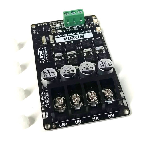
I'm attempting to drive a Cytron MD20A motor controller with the funny PWM coming from my RC receiver.

Online searching says:
"RC PWM is a pulse varying between 1 and 2ms, repeated approximately every 20ms (may be as short as 11ms or as long as 22ms)
Standard RC pulses are just a specialized form of PWM. A typical RC servo expects a signal every 20ms, however, this can vary from servo to servo. The pulse itself most often ranges from 1 ms to 2 ms, with 1.5 ms being the neutral position."
Question:
If the RC pulse width determines the direction of the motor, what determines the speed of the motor?
Is it the speed the pulses are sent?

This is the motor driver I want to use.

Project overview.
The motor controls the right and left movement of a steering axle on a robot Rover.
The brushed 10amp motor we're using was a Dewalt right angle drill in a former life.
There is a pot mounted on the steering axle that acts as a limit switch.
The inputs to the motor controller are standard PWM and a switch looking for either 5 volts to turn right or zero volts to turn left.
I'm assuming we should use a pulsin command to read the strange pwm signal from the RC receiver. Correct?

Several of you contributed to this code listed below.
Could it be adopted to this new input or would it be better to start over?
Thanks, Gramps

Code:
'Alan's cleaned up Shadow-Bot feedback control code / limits updated 11-14-20
'Note; working nice!
#picaxe 28x2
#no_data
#no_table
; The next line can reduce the PWM frequency   ** NEW ** (Cannot put comments in #define lines)
#define pwmfreq PWMDIV16,
Symbol DEADZONE = 2        ; Switch motor off (Make as small as practical)
Symbol MotorSpeed  = w4    ; (To replace the "300" in the present PWMOUT code)
Symbol LOOPGAIN = 33       ;  i.e.  MAXPWMVALUE / SLOWZONE (= 399 / 12)
Symbol PWMPERIOD = 199     ; Equivalent Max Duty Cycle is 799
Symbol desired_pot_value = b1
Symbol feedback_pot_value = b3
Symbol diff = b4
Symbol desired_pot = 13    'B.5
Symbol feedback_pot = 11   'B.4
Symbol MOTOR = B.0         ' Energize PWM
Symbol Direction = B.7
Symbol MAXPWMVALUE = 399   ; ** ONLY HALF OF THE AVAILABLE DRIVE VOLTAGE !
Symbol old_feedback_value= b5
Symbol old_desired_value= b6
Symbol ENDSTOP_A = 60      ; desired_pot MINimum value
Symbol ENDSTOP_C = 210     ; desired_pot MAXimum value
Symbol CREEP = 160         ; PWM value to run slowly * HIGH ENOUGH TO START

Main:

controlMotor1:
  Readadc Desired_pot, desired_pot_value
    Desired_pot_value = Desired_pot_value MIN ENDSTOP_A MAX ENDSTOP_C
    pause 100
    Readadc feedback_pot, feedback_pot_value
    pause 100
  If old_feedback_value<>feedback_pot_value or old_desired_value<> desired_pot_value then
    old_feedback_value=feedback_pot_value
    old_desired_value=desired_pot_value
    sertxd("Desired/Feedback: ",#desired_pot_value," ",#feedback_pot_value,13,10)
  endif
  if desired_pot_value > feedback_pot_value then
    diff=desired_pot_value - feedback_pot_value
  else
    diff=feedback_pot_value - desired_pot_value
  endif
  if diff > DEADZONE then
    MotorSpeed = diff * LOOPGAIN max MAXPWMVALUE min CREEP; Limit range of motor speed
    if  desired_pot_value > feedback_pot_value then
      high Direction                ; Set forward direction
    else
      low Direction                ; Set reverse direction
    endif
    pwmout pwmfreq MOTOR , PWMPERIOD , MotorSpeed; Slows motor within SLOWZONE  ** NEW **
  else
    pwmout MOTOR , OFF                       ; STOP
  endif
goto main
 
Last edited:

AllyCat

Senior Member
Hi,
If the RC pulse width determines the direction of the motor, what determines the speed of the motor?
Is it the speed the pulses are sent?
Not really, and No. The "funny PWM" is a Pulse Code, it is NOT a Modulation waveform intended to drive a motor directly. A code can mean whatever the sender wants it to mean, but that used to drive model-makers' Servo Motors is generally used as follows. The pulses are quite short (typically a maximum of 2.5 ms every 20 ms) so that several can be sent in sequence to represent different channels (e.g. Left/Right & Forward/Backwards or Pitch & Roll & Yaw , etc.).

Typically a 1.5ms pulse represents the "Null" state, for example neither Left nor Right, Forwards nor Backwards, Climb/Descend, etc.. Then the pulse is made shorter for one of the options (e.g. Turn Left or Go Forwards) and a longer pulse for the other option (e.g. Turn Right or Go Backwards). The more that the pulse width differs from the Null value, the greater the effect (e.g. Faster). Typically the "maximum effects" are coded by 0.75ms and 2.25ms pulses (i.e. +/- 0.75ms) and the gap between the pulses is "not significant". In practice, the decoding method may get upset if the pulses are not sent at e.g. 50 Hz, but sometimes the pulses can be just turned off to "freeze" the servo position.

Many modelling servos are now "Digital", but an analogue decoder might trigger a voltage ramp when the pulse starts, ramping from (say) Minus X volts to Plus X volts over a period of 3 ms. The ramp voltage level would be sampled when the control pulse ends and then stored as a positive or negative voltage level to determine the desired servo position. Then a comparator would compare this "desired" with the "actual" position of the motor (e.g. from a Potentiometer) to control (maybe after amplification or PWModulation) the direction and speed of the motor rotation.

In many cases, 50 Hz is too low a frequency to PWM a motor, but in principle the 0.75ms code pulse could be converted to a 0% duty cycle, 2.25ms code to a 100% duty cycle and applied to an "H-bridge" which could drive the motor forwards or backwards at any speed. However, that is not a true Servo, but roughly the equivalent of a "Continuous Rotation Servo" (i.e. a Servo with the Potentiometer removed/disabled).

With a PICaxe, a PULSIN, a little bit of maths and then a PWMOUT command may be almost all that's needed. But you might need a strategy to handle "negative" numbers. ;)

Cheers, Alan.
 
Last edited:

AllyCat

Senior Member
Hi,

Effectively yes, but in the case of a PWM H-bridge output stage (like the MD20A), a 50% duty cycle gives a half-supply voltage on each side (of the motor) to result in zero drive current. Then moving away from 50% duty cycle (in opposite directions for the two sides of the bridge) gives either a forward or reverse current flow in the motor. So in this case you don't need to worry about negative numbers as such (because they have "50%" added to them, which makes them positive).

Cheers, Alan.
 

Gramps

Senior Member
Finally back to work on this project!
The RC receiver has three connections positive, signal, and ground.
The RC signal would go to the pulsein pin. Correct?
And the ground would go to ground on the chip. Correct?
Is that all I need to get pulsein to read a signal?
I don't want to see any magic smoke here.
Gramps
p.s. results next post
 
Last edited:

Gramps

Senior Member
Code:
#picaxe 28X2
#no_data
#no_table

main:    pulsin C.3,1,w1    ; record the length of a pulse on C.3 into w1
    debug            ; report the result
    goto main        ; and repeat

    ;results
;left extreem w1=274, b2=18
;center point w1=304, b2=48
;right extreem w1=324,b2=68
[ /code]
 

AllyCat

Senior Member
Hi,
Is the signal feeding the motor in a servo PPM?
No, PPM (Pulse Position Modulation) is NOT the same as PWM (Pulse Width Modulation), and both exist in many forms.
I'm attempting to drive a Cytron MD20A motor controller .......

Then there is this part!
M51660L servo motor control chip from Mitsubish .......

;left extreem w1=274, b2=18
;center point w1=304, b2=48
;right extreem w1=324,b2=68
I think we (certainly I) need an update on the present specification. In particular where the "Servo" function is located (i.e. conversion from the "Desired Position" control signal to the Motor Speed/Direction "Power" control), the PWM frequency, and how/where the motor direction is (to be) controlled . Also I note the following from the Cyton Data Sheet:
  • PWM and DIR inputs.
  • PWM frequency up to 20kHz (Output frequency is same as input frequency).
  • Compatible with sign-magnitude and locked-antiphase PWM operation. [????]
Cheers, Alan.
 

Gramps

Senior Member
Update

we (certainly I) need an update
Sorry about my rambling.
Here's where we are ...

With a PICaxe, a PULSIN, a little bit of maths and then a PWMOUT command may be almost all that's needed.
In post #9 we were able to read the signal from the RC receiver with the pulsin command and have some usable numbers.
Here are the results
Throttle forward extreem w1=274, b2=18
Throttle off center w1=304, b2=48
Throttle reverse extreme w1=324,b2=68
Now for the math.
18*3= 54
48*3= 144
68*3= 203
Looks like that will fit in 0-255 range.

Gramps
 
Last edited:

Gramps

Senior Member
Erco wrote this sweet short code years ago. Looks like my work is done. Just replace the readadc command with pulsein and do the math to make it work!
Code:
erco's Test circuit for the DC Motor Driver MD20A

;B.5 goes to center wiper on speed control pot
;C.4 connects to direction pin on MD20A
;C.2 connects to PWM pin on MD20A

;pwmduty is 0 to 1023
#picaxe 28X2
#no_data

init: pwmout C.2,100,150 ;start pwm
main:
readadc B.5, B1 ' read pot, store ADC value 0-255 in B1
sertxd (#b1," ",#w2,13,10)
debug
if b1<128 then reeverse
foreward: high c.4: b2=b1-128: goto speed
reeverse: low c.4: b2=128-b1
speed: w2=8*b2
pwmduty C.2,w2 ; set pwm duty
sertxd (#b1," ",#w2,13,10)
debug
goto main ; loop back to start
 

Gramps

Senior Member
The results of my iron clad logic are "it doesn't work"
Somehow I have not connected the pulsin to the pwmout command.
w2 is stuck on 432 and b4 reads 176 but they do not move when i change the pulsin #.
Code:
;C.2 connects to PWM pin on MD20A
;C.3 connects to signel from the reciever
;C.4 connects to direction pin on MD20A

;pwmduty is 0 to 1023
#picaxe 28X2
#no_data
#no_table

init: pwmout C.2,100,150 ; start pwm
main:    pulsin C.3,1,w1    ; record the length of a pulse on C.3 into w1
    debug            ; report the result
    sertxd (#b1," ",#w2,13,10)

if b2<144 then reeverse

foreward: high c.4: b2=b1-144: goto speed
reeverse: low c.4: b2=144-b1

speed: w2=3*b2
pwmduty C.2,w2 ; set pwm duty
    ;debug            ; report the result
sertxd (#b1," ",#w2,13,10)

goto main ; loop back to start
    ;results
;center point w1=304, b2=48
;left extreem w1=274, b2=18
;right extreem w1=324, b2=68

;Now for the math.
;18*3= 54
;48*3= 144
;68*3= 203
 

neiltechspec

Senior Member
W0 is B0 & B1
W1 is B2 & B3

As you capturing the pulse into W1, should you not be looking B2 & B3 ?.
B0 & B1 will be always 0.
 

AllyCat

Senior Member
Hi,
[Post #1]
Project overview.
The motor controls the right and left movement of a steering axle on a robot Rover.
[and post #11]
Throttle forward extreem w1=274, b2=18
Throttle off center w1=304, b2=48
Throttle reverse extreme w1=324,b2=68
[and post #12]
;pwmduty is 0 to 1023 ......
init: pwmout C.2,100,150 ;start pwm
Personally, I'm confused by the apparent conradictions in #1 and #11. Also, there is no need to use both SERTXD and DEBUG commands in consecutive lines, which basically provide the same data but might produce some system "confusion" because they both use the same PICaxe output pin.

Indeed, as neil says, b1 (as a component of w0) doesn't appear to be receiving any input data, and it's generally poor practice to just "ignore" the high byte of a word variable (when, as here, it's not zero). If you want to subtract 256 from a variable, then in most cases that's the way it should be coded (i.e. w1 = w1 - 256) ! Also note that in post #12, the PWMOUT instruction is setting a maximum PWMDUTY of 403 (i.e. 100 + 1 * 4 -1) not 1023 (i.e. 255 + 1 * 4 -1).

Cheers, Alan.
 

Gramps

Senior Member
ject overview.
The motor controls the right and left movement of a steering axle on a robot Rover.
My apologies Alan, i started this thread Oct 16, but by the time i got to post #11 i went from left to right to forward and reverse!
But it is left to right as originally posted.

ho need to use both SERTXD and DEBUG
Correct. Was trying it both ways but forgot to comment them out.
 

lbenson

Senior Member
Note that DEBUG is notorious for causing unexpected problems with timings. I personally never use it--always use SERTXD to get just the information needed.
 

Gramps

Senior Member
-always use SERTXD
Why doesn't the Editor pop up the serial terminal when the code runs?
Opened it manually and changed the baud rate to 9600 to get real results but it works!
Code:
'USING PLUSIN TO READ THE RC RECIEVER
#picaxe 28X2
#no_data
#no_table
Symbol PULSIN_RC = C.3 ;Read RC signel
Symbol valuePulsin = w1
main:
    pulsin PULSIN_RC, 3, valuePulsin
   
      sertxd("The value of b2 is ",#b2,13,10)
      pause 1000
           
goto main
 

Gramps

Senior Member
W0 is B0 & B1
W1 is B2 & B3

As you capturing the pulse into W1, should you not be looking B2 & B3 ?.
B0 & B1 will be always 0.
IT'S WORKING!!!!!!
Code:
;C.2 connects to PWM pin on MD20A
;C.3 connects to signel from the reciever
;C.4 connects to direction pin on MD20A

;pwmduty is 0 to 1023
#picaxe 28X2
#no_data
#no_table
#terminal 9600


init: pwmout C.2,100,150 ; start pwm
main:    pulsin C.3,1,w1    ; record a pulse on C.3 into w1

    sertxd (#b2," ",#w2,13,10)
pause 1000
if b2<48 then reeverse

foreward: high c.4: b2=b2-48: goto speed
reeverse: low c.4: b2=48-b2

speed: w2=8*b2
pwmduty C.2,w2 ; set pwm duty

pause 1000
goto main 
    ;results
;center point w1=304, b2=48
;left extreem w1=274, b2=18
;right extreem w1=324, b2=68
{/code]
 

erco

Senior Member
EDIT: Oops, look like you already solved it. Congrats!

Hey Gramps, try this. Untested, I took a quick swag at it. I have no hardware handy.

Code:
;C.2 connects to PWM pin on MD20A
;C.3 connects to signal from the receiver
;C.4 connects to direction pin on MD20A

'28X2 default speed is 8Mhz
'PWM frequency 500Hz  (slowest)
'10%=pwmout pwmdiv16, C.2, 249, 100  
'50%=pwmout pwmdiv16, C.2, 249, 500
'100%=pwmout pwmdiv16, C.2, 249, 1000

;pwmduty is 0 to 1023
#picaxe 28X2
#no_data
#no_table


init: pwmout pwmdiv16, C.2, 249, 100 ; start pwm 500Hz 10%

main:    pulsin C.3,1,w1    ; record the length of a pulse on C.3 into w1
sertxd (#w1,13,10)  'for 1-2 ms servo pulsewidths, w1 should measure from 200-400, 300=center off

if w1<300 then reeverse

foreward: high c.4: b10=w1-300: goto speed
reeverse: low c.4: b10=300-w1
'now 0<b10<100

speed: w2=10*b10 'now 0<w2<1000  NOT QUITE 1024 full range
pwmduty C.2,w2 ; set pwm duty

sertxd (#w2,13,10)

goto main ; loop back to start
 
Last edited:

erco

Senior Member
Try this, Gramps:

Code:
'28X2 default speed is 8Mhz
'PWM frequency 500Hz  (slowest)
'10%=pwmout pwmdiv16, C.2, 249, 100  
'50%=pwmout pwmdiv16, C.2, 249, 500
'100%=pwmout pwmdiv16, C.2, 249, 1000

;pwmduty is 0 to 1023

'per Gramps:
'left extreme w1=274, b2=18
'center point w1=304, b2=48
'right extreme w1=324,b2=68


#picaxe 28X2
#no_data
#no_table


init: pwmout pwmdiv16, C.2, 249, 100 ; start pwm 500Hz 10%

main:    pulsin C.3,1,w1    ; record the length of a pulse on C.3 into w1
sertxd (#w1,13,10)  'for 1-2 ms servo pulsewidths, w1 should measure from 274-324, 304=center off

if w1<304 then reeverse

foreward: high c.4: b10=w1-304:w2=51*b10 :goto speed  'range=20
reeverse: low c.4: b10=304-w1:w2=34*b10   'range=30
'now 0<b10<100

speed: 'w2=10*b10 'now 0<w2<1000  NOT QUITE 1024 full range
pwmduty C.2,w2 ; set pwm duty

sertxd (#w2,13,10)

goto main ; loop back to start
 

erco

Senior Member
Also a high frequency hum from the motor.
That sound is the high PWM rate, but that's the slowest PWM rate a 28X2 can give at 8MHz: 500 Hz. I generally prefer 100 Hz or lower. If it gives you problems we can slow down the Picaxe for lower PWM.
 

Gramps

Senior Member
Try this, Gramps:
Code is working better. Approximately 100 RPM at full speed on the right turn. Nicely proportional, too!
How to change the RPM to say200?
Not a big deal but the neutral point is bouncing off and on.
Left turn is 50% slower then right turn.
When the control lever springs back to neutral, I'd like the steering to return to the center point!
 

erco

Senior Member
When the control lever springs back to neutral, I'd like the steering to return to the center point!
Sorry but I'm utterly lost here. This code is to control a motor speed controller. Is there also a steering servo somewhere that you are referring to? Please send some photos or sketches of the chassis you're working on and describe your goal.
 

Gramps

Senior Member
I'm utterly lost here.
erco, sorry for the confusion, It's my fault.
This is from my original post.
Project overview.
The motor controls the right and left movement of a steering axle on a robot Rover.
The brushed 10amp motor we're using was a Dewalt right angle drill in a former life.
There is a pot mounted on the steering axle that acts as a limit switch.
 

erco

Senior Member
Neat rover. So basically you are making a linear servo for steering. I'd focus less on speed control, you likely only need 3 or 4 speeds. I'd focus on the feedback/control system, you have some heavy parts there and there will be overshoot & oscillation. You'll want high speed to travel big distance then slow down as you approach the target position. And with a big motor you'll definitely want lower PWM speed than 500 hz, which AFAIK is the slowest a 28X2 can do running at 8 MHz. You can run it at a lower frequency for better PWM control but then SERVO commands won't work, if you plan to use those. You may want to use a dedicated chip like an 08M2 just for steering.
 

erco

Senior Member
I would have just gutted a big servo and used the circuit board with your motor and steering pot.
 

Gramps

Senior Member
Some ideas for attachments to the Robot Rover.
Power and push the lawn mower
Push the snow blower
Run the Leaf blower
Push a wheelbarrow
Pull a small trailer
Small forklift attachment
Move the firewood up to the house
Water the garden
Stand guard duty
Patrol the driveway
Walk the dogs
Telepresence
 

Gramps

Senior Member
Quick Products JQ-3000 Power A-Frame Electric Tongue Jack with LED Work Light and Permanent Ground Wiring for Camper Trailer, RV, Ice House - 3,250 lbs. Lift Capacity https://a.co/d/fX4qEqM
I think this would make a nice power assembly for the forklift that moves the firewood bundles.
 

papaof2

Senior Member
You might need to be able to tilt the fork lift arms slightly below horizontal to get them under a stack of firewood and then tilt them up enough to keep the firewood on the arms while it's being moved. How much movement do you need at the point of drive attachment to move the arms through that range of angles? How much load would be on the arms so how much power and how much movement range would be needed to move the back end of the fork lift arms through that range of motion? The electrical equivalent of hydraulic cylinders and a motion-capable mounting for each end of the cylinders - a through-hole with a sturdy pivot pin is likely all that's needed.
I won't even attempt an ASCII drawing of that.
 

Gramps

Senior Member
to tilt the fork lift arms
That's correct. Looked at two basic designs for forklifts online. Both of them use two hydraulic cylinders, one for lifting and the other for tilt.
A liftgate actuator from the junkyard might work for the tilt mechanism.
30 pounds max would be the carrying capacity.
attempt an ASCII drawing
I have a very old but reliable SketchUp program that I use for these applications. The media is made of tree fibers and the stylus is composed of graphite, clay and wax.
Gramps
 

Gramps

Senior Member
12V DC Power Seat Motor Worm Motor,Worm Drive Right Hand Configuration https://a.co/d/fFuqcS5
This little worm drive has about 2 and 3/8 inches of throw but that would probably be enough to tip the forks. And it is considerably cheaper than a liftgate actuator.
 
Top