R/C network question

Andrew Cowan

Senior Member
I am trying to create a rough, moderatly high power pot using a FET.

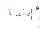
I am putting the output of an 08M through a 380 ohms resistor into the gate of the FET. The FET has a 0.47uF capacitor on it (to ground), and a 22K drain resistor.

However, this seems to charge up too easily. What values of R and C would you recommend for this? I am basically tring to create an analogue voltage of 0-5V. Is a drain resistor needed? Is the 1K resistor needed, or should I PWM straight into the cap?

Thanks,

A
 

Attachments

Last edited:

BeanieBots

Moderator
You're a little vague about your requirements.

For the PWM part, your RC value should have a time constant of around 10 times that of the PWM period. Obviously, going higher will reduce the ripple but will also reduce response time. Depends which is the more important to you. PWM into RC for voltage does NOT need a drain resistor because it is a totempole output. Any drain resistor on the cap will simply give potential divider action and reduce the RC time constant as the total load impedance on the C is reduced.

As for the "POT" part, you will be aware of the Gate voltage vs Ron characteristic curve for your specific FET and what other effects influence its shape. IF that suits your needs then fine.
 

Andrew Cowan

Senior Member
Thanks Bb - I think that solves everything. Responce time isn't important, so'll go with a highish time constant.

I'm measuring the resistance given off, so Vgate vs Ron curves don't affect anything.

A
 

inglewoodpete

Senior Member
Andrew, If you don't use a diode in series with R1 to charge the capacitor, then the capacitor will discharge back into the PICAXE when the output goes low. R2 is 60 times R1 so will have very little effect on the circuit as drawn.

As an aside, where did you get a 380 ohm resistor from - I've never heard of that value!! Back to check the colour codes again?
 

BeanieBots

Moderator
The discharge is ESSENTIAL for converting PWM to voltage.
Fitting a diode and drain resistor will make it never capable of reaching 5v.
 

fernando_g

Senior Member
You're a little vague about your requirements.


As for the "POT" part, you will be aware of the Gate voltage vs Ron characteristic curve for your specific FET and what other effects influence its shape. IF that suits your needs then fine.

As Beanie mentions, this is quite important.
Select a Mosfet with a higher Vgs(th) value. Most of the newer Mosfets are "logic level" devices, some of which begin to turn-on with voltages as low as 0.8 volt.
Do you have the Mosfet part number that you intend to use?
 

Andrew Cowan

Senior Member
It is a logic level FET - the P36nf06l. It works fine - and I can fully adjust the voltage of the cap. I only want to adjust the resistance between fully on and a few ohms. This is achieveable with my current setup.

The resistor is a 5% 390 ohm resistor, so 380 is within its tolerence.

Thanks again,

A
 
Top