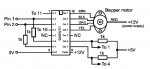
Pin1 and Pin2 are inputs from your Picaxe, whatever type you have ?. Edit: for clarification, the driver signal from the Picaxe to the ULN2003./Edit
The other "To" pins 11, 10, 1 and 4 are connections back to the same chip the ULN2003.
The ULN2003 is a 16 pin chip.
Have another Cofféé and all wil be revealed
Since the code below uses the "toggle" command, Pin 1 and Pin 2 should work for any standard outputs on any picaxe. According to the table shown, pins 1 and 2 would activate or deactivate coils 1 and 3.
Since leg 10 says "To 4" and leg 4 says "To 10", I would assume the legs were to be connected. Same with 1 and 11.
Pin 1 and Pin 2 can be any two "standard" PICAXE outputs.
Just change the numbers in the associated TOGGLE statements in the code example further down the page to reflect the two outputs that you use.
Definitely "To 1" means wire to physical Pin1 of the ULN2003.
"To 4" means to physical Pin 4 of the ULN2003
etc
I have used this very circuit to drive a stepper motor in an old flatbed scanner that has a string of uv leds in place of the normal white light to expose printed circuit board artwork.
Two versions one with on 08M the other a 14M with no problems using output pins 1 and 2 in each case to drive the uln2003 into Pin 1 and Pin 2.
As noted in previous post physical pin 1 of the 2003 is connected to physical pin 11 which also has a 1K resistor connected to the 5 volt supply.
The same with pin 4 of the uln it is connected to pin 10 which also has a 1K to 5 volts.
In my particular case the software at the bottom of page 15 works except the pause command is only 1 in both cases, this was required to make the stepper rotate continuosly.
Hope this is of some help.
 82.1 KB Views: 46
")