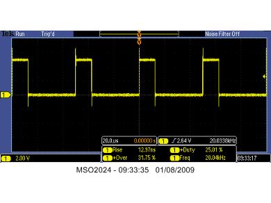
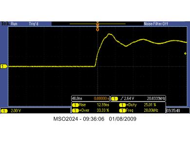
I'm using 18x chip with the CH1030 project board, and cannot get the pwmout pulses to work! Depending on period, mark/space ratios all I get is narrow pulses that rise in amplitude rather than width, or arising voltage with triangular waveform on top.
Simple high/low on an output pin works perfectly on scope display.
for evaluation purposes I use
init: let b0=0
start:let b0=b0+1
pwmout 3 , 255, b0
if b0>1022 then init
pause 100
goto start
Later I just used the pwmout insruction as a static one line statement , so there would be no other 'timing' conflicts still same problems. All other aspects work perfectly. I've even used another 18x chip still same result. I'm slowly gonig mad! Hope someone can come up with solution
")