PWM output on a -08M
- Thread starter PIK-E
- Start date
BeanieBots
Moderator
Welcome to the forum.
The syntax is:-
PWM pin,duty,cycles
PWM is the command, pin,duty & cycles can be constants OR variables.
What other input do you need/want?
The syntax is:-
PWM pin,duty,cycles
PWM is the command, pin,duty & cycles can be constants OR variables.
What other input do you need/want?
I'm using the Logicator to get me started, but all it lets you do is 0-100 duty, no dropdown for a variable. Unless the dropdown gets filled up as you define variables in Logicator, but haven't tested that to see if that's the case...Welcome to the forum.
The syntax is:-
PWM pin,duty,cycles
PWM is the command, pin,duty & cycles can be constants OR variables.
What other input do you need/want?
THANKS!
Two points.I'm using the Logicator to get me started, but all it lets you do is 0-100 duty, no dropdown for a variable. Unless the dropdown gets filled up as you define variables in Logicator, but haven't tested that to see if that's the case...
THANKS!
1. Can you provide more background information
about your project / requirements?
2. Seriously consider using BASIC.
")
Manual 2, page 160.
And the "Wizard" from Programming Editor.
e
westaust55
Moderator
The PWM command only produces a short burst of output and then the pin returns to an input state on the 08M
The PWMOUT command sets up the internal hardware so that the PWM output signal continues at the set rate until changes or stopped by a new PWM command.
You indicate you are using Logicator.
Unfortunately for you, the majority of PICAXE users do seem to use the text based Programming Editor. As such I cannot comment specifically on what can be done in Logicator.
Last edited:
http://www.rev-ed.co.uk/docs/cat_06.pdfWhat is Logicator? Is that another term for the flowsheet design?
You can use pwmout with a variable in Logicator, but it is much more complicated (as Logicator normally calculates the pwmout command values using an equation automatically in the background (from the percentage you enter)).
To do this use a BASIC Logicator cell and a command typed in such as
pwmout 2,100,varA
You will need to look up the pwmout command in part 2 of the manual to work out the correct values to use (or use the Programming Editor wizard).
Or create a flowchart with two pwmout cells (1% and 100%) and convert this existing Logicator flowchart to BASIC and have a look at the pwmout command that was automatically generated - this will give you an idea of the the values to use.
To get started I was looking to read an analog voltage on a pin and output a PWM in relation to it.Two points.
1. Can you provide more background information
about your project / requirements?
2. Seriously consider using BASIC.
Manual 2, page 160.
And the "Wizard" from Programming Editor.
e
Thanks!
PIK-E.To get started I was looking to read an analog voltage on a pin and output a PWM in relation to it.
Thanks!
Logicator, AFAIK, is a superb program for initial education.
For your simple voltage - pwm however,
try something like:
Code:
#picaxe 08M

Main:

readadc 1,b0 ;	Reads a value between 0-255

pwmout 2, 62, b0;	outputs value
;			Varies LED brightness from off(0) to full(255)

pause 100 ;		pause for 1/10th sec.

goto Main ; start againAll right, now things are starting to work, any idea why pause doesn't pause? I played around with the values, but no affect on PWM frequency. Is the PWM frequency fixed for the PWMOUT function block? Or does pause only affect the time it takes to update the PWMOUT block?PIK-E.
Logicator, AFAIK, is a superb program for initial education.
For your simple voltage - pwm however,
try something like:
eCode:#picaxe 08M Main: readadc 1,b0 ; Reads a value between 0-255 pwmout 2, 62, b0; outputs value ; Varies LED brightness from off(0) to full(255) pause 100 ; pause for 1/10th sec. goto Main ; start again
THANKS!!
hippy
Ex-Staff (retired)
Not sure I fully understand the question but you've perhaps misunderstood how PWMOUT works. The second parameter (62) sets the frequency, the third (b0) sets the duty cycle.All right, now things are starting to work, any idea why pause doesn't pause? I played around with the values, but no affect on PWM frequency. Is the PWM frequency fixed for the PWMOUT function block? Or does pause only affect the time it takes to update the PWMOUT block?
THANKS!!
The PAUSE statement you have affects how quickly the "Main: ... goto Main" loop repeats, how frequently the READADC is read and how frequently the PWMOUT duty is updated.
Interrupting
Got it. I found out the pause thing by changing it a few times and tweaked the voltage while watching the PWM change.
The only other problem I ran into afterwards is using the interrupt function with the Logicator. It doesn't stop the PWM output, only the ADC from updating it. I figured if I tried to poke the variable to 0, the duty cycle would go to 0 but that didn't work either.
Does it have to do with having the PWMOUT in basic instead of a Logicator block?
I have the interrupt enabled after start then the program to generate the PWM duty from the ADC variable. The interrupt function is separate (wired with poke and return) and looks for a 1 on input 4 to go high, then I poke the memory to 0 and return. My thought was if the pin was held high it would force the duty cycle to 0 over a few cycles.
Ideas?
THANKS!
hippy
Ex-Staff (retired)
I don't understand your "poke" terminology but if you execute -
PwmOut 2, 63, 0
or
b0 = 0
PwmOut 2, 63, b0
those will set the duty to zero.
If you are trying to set the duty to zero by using ...
PwmOut 2, 63, b0
b0 = 0
Then that won't work; the PWM is set only when the PWMOUT command executes. Altering variables afterwards will not affect the PWM output.
PwmOut 2, 63, 0
or
b0 = 0
PwmOut 2, 63, b0
those will set the duty to zero.
If you are trying to set the duty to zero by using ...
PwmOut 2, 63, b0
b0 = 0
Then that won't work; the PWM is set only when the PWMOUT command executes. Altering variables afterwards will not affect the PWM output.
Last edited:
Ok, I'm using the Logicator to program the pic and generate this code, what seems odd is that input 4 seems undefined when it should be set as the interrupt input. The basic function is to get a voltage on the adc 1, scale it, produce a pwm output and have input 4 be able to interrupt it:
let dirs = %00000001
main:
setint 16,16 'enable the interrupt
label_80: readadc 1,varA
let varA = varA + 10 'Expression command
interrupt:
poke varA,0
pwmout 2, 71, b0; Port/Period uS/Variable
; Varies LED brightness from off(0) to full(255)
pause 100 ;pause for 1/10th sec.
goto label_80
let dirs = %00000001
main:
setint 16,16 'enable the interrupt
label_80: readadc 1,varA
let varA = varA + 10 'Expression command
interrupt:
poke varA,0
pwmout 2, 71, b0; Port/Period uS/Variable
; Varies LED brightness from off(0) to full(255)
pause 100 ;pause for 1/10th sec.
goto label_80
hippy
Ex-Staff (retired)
I'm afraid your code does not make a lot of sense. You cannot use an interrupt routine in the way you are doing - it should be a separate subroutine in its own right, ending with a RETURN and also probably issuing a SETINT to accept further interrupts - you cannot 'fall into' the interrupt as you are doing nor can you GOTO out of the interrupt routine. Also the "POKE" makes no sense; you probably meant "let varA = 0".
It's hard to give an example which would work because it's not clear exactly what you are trying to achieve. What do you want to happen when pin 4 goes high ? Presumably you want to set the duty to zero, but then what ?
You probably don't even need interrupt. You could check what the level of Pin 4 is within your main loop.
Agreed, as far as the interrupt goes, I was trying to force it to work. Even with it configured as this below, still no override of the main program based on the interrupt input.I'm afraid your code does not make a lot of sense. You cannot use an interrupt routine in the way you are doing - it should be a separate subroutine in its own right, ending with a RETURN and also probably issuing a SETINT to accept further interrupts - you cannot 'fall into' the interrupt as you are doing nor can you GOTO out of the interrupt routine. Also the "POKE" makes no sense; you probably meant "let varA = 0".
It's hard to give an example which would work because it's not clear exactly what you are trying to achieve. What do you want to happen when pin 4 goes high ? Presumably you want to set the duty to zero, but then what ?
You probably don't even need interrupt. You could check what the level of Pin 4 is within your main loop.
symbol varA = b0
saving posting space (deleted 1-6)
symbol varH = b7
let dirs = %00000001
main:
setint 16,16 'enable the interrupt
label_80: readadc 1,varA
let varA = varA + 10 'Expression command
pwmout 2, 71, b0; Port/Period uS/Variable
; Varies LED brightness from off(0) to full(255)
pause 100 ;pause for 1/10th sec.
goto label_80
interrupt:
let varA = 0 'Expression command
return 'Return
hippy
Ex-Staff (retired)
The problem is that you enter the interrupt, set varA = 0, return to somewhere in the main loop, and some short time later re-read the ADC into varA and set the PWMOUT from that varA+10, which will no longer be zero.
What exactly are you trying to achieve ? What do you want to happen when pin 4 goes high ? What do you want to happen after that ?
What exactly are you trying to achieve ? What do you want to happen when pin 4 goes high ? What do you want to happen after that ?
I was shooting for (Input) 4 interrupting the main PWMOUT loop, setting PWMOUT to 0 and looping there until the micro was reset. I thought that once I set the varA to 0 that on the next cycle it would be 0, but it wasn't reduced by any amount.The problem is that you enter the interrupt, set varA = 0, return to somewhere in the main loop, and some short time later re-read the ADC into varA and set the PWMOUT from that varA+10, which will no longer be zero.
What exactly are you trying to achieve ? What do you want to happen when pin 4 goes high ? What do you want to happen after that ?
Thanks for your help!
Perhaps you could do two things:I was shooting for (Input) 4 interrupting the main PWMOUT loop, setting PWMOUT to 0 and looping there until the micro was reset. I thought that once I set the varA to 0 that on the next cycle it would be 0, but it wasn't reduced by any amount.
Thanks for your help!
1. Post a circuit / schematic / HQ photograph of your setup.
2. Use five or six short, linked
bullet point statements,
in straightforward English (not BASIC),
explaining your requirements.
e
1) Unfortunately all I have is the PicAxe proto-board connected to a larger breadboard with a pot, resistor & LED, and a small scope to take a look at. I wanted to see functionality, hence the breadboard.Perhaps you could do two things:
1. Post a circuit / schematic / HQ photograph of your setup.
2. Use five or six short, linked
bullet point statements,
in straightforward English (not BASIC),
explaining your requirements.
e
2) Here goes:
* Pot wiper is connected to Pin6 (aka port1), with + & - pot connections to + and - on the PicAxe board
* LED is connected to pin5 (aka port2) as PWMOUT, with a series 390 ohm to Anode, Cathode to board -.
* Capture voltage on pot wiper, as a variable on port1
* Scale variable with expression
* PWMOUT the result on port 2
* Interrupt to stop PWM (force to 0)
I was going to see what the delay time was from interrupt to PWMOUT.
Since that doesn't seem to work at the moment, I'm stuck.
hippy
Ex-Staff (retired)
Well that's relatively easy if you think of it in terms of 'generate PWM until pin 4 goes high, then stop PWM, and do nothing more. In Basic but I'm sure you'll figure how to turn it into flowchart blocks ...I was shooting for (Input) 4 interrupting the main PWMOUT loop, setting PWMOUT to 0 and looping there until the micro was reset.
label_80:
readadc 1,varA
let varA = varA + 10
pwmout 2, 71, b0
pause 100
If pin4 <> 1 goto label_80
pwmout 2, 71, 0
label_81:
goto label_81
It looks like I have something finally working. Guess I have a long way to go in order to 'see' what the micro is expecting vs what I want it to do.Well that's relatively easy if you think of it in terms of 'generate PWM until pin 4 goes high, then stop PWM, and do nothing more. In Basic but I'm sure you'll figure how to turn it into flowchart blocks ...
label_80:
readadc 1,varA
let varA = varA + 10
pwmout 2, 71, b0
pause 100
If pin4 <> 1 goto label_80
pwmout 2, 71, 0
label_81:
goto label_81
Here's what works, with Port4 as my interrupt. Still have to see how fast it is, so that's my next step.
let dirs = %00000001
main:
label_80: readadc 1,varA
readadc 4,varB
let varA = varA + 1 'Expression command
if varB > 126 then label_102 'Compare command
pwmout 2, 71, b0; Port/Period uS/Variable
; Varies LED brightness from off(0) to full(255)
pause 100 ;pause for 1/10th sec.
goto label_80
label_102: pwmout 2 , 99 , 0
goto label_80
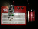
I'd like to do a pic, but it seems rather boring to just have a board, pot, LED and wires...The PCB is a PicAxe-08 Proto board.
hippy
Ex-Staff (retired)
But not if you are after the specification given in an earlier post - "I was shooting for (Input) 4 interrupting the main PWMOUT loop, setting PWMOUT to 0 and looping there until the micro was reset."It looks like I have something finally working.
The problem is that you have a "goto label_80" at the end after setting PWM duty to zero. That's not a "looping there until reset", that's going back and setting the PWM duty according to the READADC ( albeit with an aside of PWM duty forced to zero while pin4 is high ).
If there's a disparity in specification and 'working code' it becomes impossible for anyone to really tell what you want or wanted, to know which is right. This is why it's very important to know and define exactly what you want, then to create the code to exactly what you want.
I agree, i guess i jumped to it working as far as i could actually get the PWM to 0 with input 4 input high. That was a first over 20 or more other attempts to make it do that. Its a milestone when it responds vs doing nothing. Sure, I would like to have it hang there till reset. True, I still need to loop until reset, and test how long it takes to get to 0 PWM so there's more for me to do. Logicator doesn't offer as much versatility for doing what I'm after, and my basic programming skills are still nil, I was hoping to use logicator to allow me to draw up in a flow chart manner (similar to labview) and looking at code via Logicator is a great idea since you have a flow and code representation together. I seem to have found its limitation forcing me into basic much sooner than I would like.But not if you are after the specification given in an earlier post - "I was shooting for (Input) 4 interrupting the main PWMOUT loop, setting PWMOUT to 0 and looping there until the micro was reset."
The problem is that you have a "goto label_80" at the end after setting PWM duty to zero. That's not a "looping there until reset", that's going back and setting the PWM duty according to the READADC ( albeit with an aside of PWM duty forced to zero while pin4 is high ).
If there's a disparity in specification and 'working code' it becomes impossible for anyone to really tell what you want or wanted, to know which is right. This is why it's very important to know and define exactly what you want, then to create the code to exactly what you want.
OK fine.I agree, i guess i jumped to it working as far as i could actually get the PWM to 0 with input 4 input high. That was a first over 20 or more other attempts to make it do that. Its a milestone when it responds vs doing nothing. Sure, I would like to have it hang there till reset. True, I still need to loop until reset, and test how long it takes to get to 0 PWM so there's more for me to do. Logicator doesn't offer as much versatility for doing what I'm after, and my basic programming skills are still nil, I was hoping to use logicator to allow me to draw up in a flow chart manner (similar to labview) and looking at code via Logicator is a great idea since you have a flow and code representation together. I seem to have found its limitation forcing me into basic much sooner than I would like.
Then start again in BASIC,
you'll then get more help,
and please post the schematic and photographs.
"boring" or not,
they will help others to help you
rather than chasing a moving target.
e
Pic of PicOK fine.
Then start again in BASIC,
you'll then get more help,
and please post the schematic and photographs.
"boring" or not,
they will help others to help you
rather than chasing a moving target.
e
Schematic? I'm still figuring out how these work. Once I see its going to work I can draw up something to try out. I was thinking of using one to control an IGBT eventually, but I have to see how it does on the bench with a few external stimuli before I attempt to control something else.
One thing that came to mind in all this is the ideal time as to when to look at input 4. I figure when the PWM output is high would be ideal. Even if its not possible I could buffer when input 4 goes high with a cap long enough to see it afterwards and shutdown the PWM.
Once I see it can do the job on the bench, then I'll set it up to drive a IGBT (level shifted and buffered of course) and see how it controls it. More photos and waveforms will be posted as this progresses.
THANKS!
hippy
Ex-Staff (retired)
I'm not sure what your thinking is here but PWM will always be high ( well, always active whenever you have it on ). As Input 4 is independent of PWM you can read it at any time you choose to and I cannot see any reason for having to hold the input with a cap.One thing that came to mind in all this is the ideal time as to when to look at input 4. I figure when the PWM output is high would be ideal. Even if its not possible I could buffer when input 4 goes high with a cap long enough to see it afterwards and shutdown the PWM.
Does what you have so far not do what you want ? In what way is it not working, and why do you think you need to read input 4 when PWM is high or add a cap ?
Perhaps you should explain what it is your project is intended to do. You seem to be making things far more complicated than they need to be.
Hi,
This is some code i wrote to run a model railway. I am delighted with the results. Just got to get the Picaxe running from a ML7805 or similar. At the moment the Voltage regulator is getting very hot!
Stuart
main:
W0=420 'set pwm duty
pwmout 2,189,650 'kick start motor
start:
if pin3 =1 then kill 'emergency brake
if pin1 =1 then increase'faster
if pin4 =1 then decrease'slower
goto motor
increase:
if W0<420 then kick 'if duty cycle <420 kickstart to overcome internal resistance
W0=W0+3 max 756 'increment duty cycle max 4x period 756
goto motor
decrease:
b2=b2+1
if W0 =420 and b2 >=3 then dye 'stop engine after 3 cycles at lowest speed setting
W0=W0-3 min 420 'decrement duty cycle motor stall <420
goto motor
motor:
debug
pwmout 2,189,W0 'pwm cycles to pin 2
pause 5
goto start 'check switch settings
kill:
W0=420
pwmout 2,0,0 'kill pwm to motor
High 0 'flash LED
pause 20
low 0
pause 20
goto start
dye:
pwmout 2,0,0
High 0 'flash LED
pause 20
low 0
pause 100
if pin4 =1 then decrease'check switch setting
goto start
kick:
pwmout 2,189,650 ' kick start motor
goto increase
radiogareth
Senior Member
I am using an 08M to drive a 1 watt led thropugh a driver transistor.
Main:
readadc 4,b0 'reads the voltage on the A to D from potentiometer
if b0>253 then let b0=253 'To make sure that we do not overflow
endif
if b0<10 then let b0=0 'To makes sure that it can actually switch off
endif
pwmout 2, 62,b0 ' Does it
goto main 'Goes back and does it again
At low pwm's I am getting flicker, despite setting the frequency to 15.8KHz via the wizzard.
Can anyone tell me why?
I chose the frequency to (a) try and stop flicker and (b) so that it gave me a handy value in B0 that did not need further procesing. The upper and lower limit adjust are just to make sure it can be 100% on and completely off.
TIA
Gareth
Hi Gareth,
I initially assumed that the values would go from 0 - 1000, 0 off, 1000 full on. Now i am talking about a motor for the most part but i initially used an LED to see what was happening.
I found that I had to have the period set at 99 and the duty try different values until something fires te find the highest value and the lowest value that i had a result. your start point may be a lot higher than 0!
Stu
radiogareth
Senior Member
Had a play this lunchtime, removing waste code in an attempt to reduce flicker. I slowly tweaked the PWM frequency (in wizard) until I got 255@100%, so negating the possibility of roll-over.
Then I wondered if I would 'wear out' the B0 storage area with it looping round so fast!
Any suggestions?
Main:
readadc 4,b0 'reads the voltage on the A to D from potentiometer
if b0<5 then let b0=0 'so it goes OUT
endif
pwmout 2, 63, b0 ' Does it
goto main 'Goes back and does it again
Still flickers in the bottom 15% of the PWM?? Tried a capacitor across the led pins (10uF), still the same. It got brighter but could still be seen flickering. Am I maybe expecting too much?
TIA
Gareth
hippy
Ex-Staff (retired)
You won't wear b0 or any of the other variables out.
The problem may be that you are repeatedly executing PWMOUT and quite quickly. Unfortunately there is no PWMDUTY command for the 08M but there may be ways round that. In the meantime, I'd suggest adding a PAUSE 100 before the GOTO MAIN - It will make response to the pot slightly sluggish but ignore that, let's see if it improves the flicker.
The problem may be that you are repeatedly executing PWMOUT and quite quickly. Unfortunately there is no PWMDUTY command for the 08M but there may be ways round that. In the meantime, I'd suggest adding a PAUSE 100 before the GOTO MAIN - It will make response to the pot slightly sluggish but ignore that, let's see if it improves the flicker.
radiogareth
Senior Member
Thanks Hippy, that sort of helps but it looks like something counts up and every few seconds there is a big flicker. I think a better way might be to readadc, output the value but only issue a pwmout command IF the adc value changes ie jump to a new procedure with the pwm commnad in it ONLY IF the value has changed. That way once set, it will just sit there doing it.
Slight change of code: remove goto main and replace with end
<<<<Pause to download>>>>>
Does not work, it seems to need to constantly issue the pwmout command which is not how I read the manual. I thought once it was running it was fine?
However:
main:
pwmout 2, 62, 1
goto main
works fine with no flicker so I think it must be code execution overheads getting in the way of things and only showing when the pwm is very low MARK:SPACE.
Will try writing my idea above next....
Ta
Gareth
radiogareth
Senior Member
And in answer to myself:
Main:
let b1=b0
readadc 4,b0
if b0=b1 then goto main
goto lightmeup
Lightmeup:
pwmout 2, 63, b1
goto main
This works much better, although at certain low duty settings there is a slight flicker but a tiny tweak on the pot solves that. It seems that so long as the picaxe is 'doing something' the pwm continues to run, even though the pwmout command is not in the running loop. Maybe I need a clearpwmtimer command or something??
As a guess I'd think it's software getting in the way of something (itself) but will read suggestions with interest, and implement solutions with pleasure!
Gareth
hippy
Ex-Staff (retired)
A cap on the ADC input might help and perhaps a bit of software filtering. With high brighteness and low PWM duty there can be flicker in lamps anyway and the re-issuing PWMOUT can sometimes add some which I think is what you are seeing.
You can optimise your code a little which may make things clearer and smoother ( or may make it worse ! ) ...
It may also be worthwhile upping the "63" frequency to 255 and trying this ...
Or even ...
You can optimise your code a little which may make things clearer and smoother ( or may make it worse ! ) ...
Code:
Do
  ReadAdc 4, b0
  If b0 <> b1 Then
    b1 = b0
    PwmOut 2, 63, b1
  End If
Loop
Code:
Do
  ReadAdc 4, b0
  w1 = b0 * 4
  If w1 <> w2 Then
    w2 = w1
    PwmOut 2, 255, w2
  End If
Loop
Code:
Do
  ReadAdc10 4, w1
   If w1 <> w2 Then
    w2 = w1
    PwmOut 2, 255, w2
  End If
Loopradiogareth
Senior Member
Thanks for the tips, I'll try today inbetween classes (I teach)@Gareth,
just for information,
could you post the circuit for your project?
e
As for a circuit, I don't have a drawn version, but it's based on the Kitronik project board which uses output pin 2 to drive a BC337 via a 1k. The transistor switches to ground from positive. The collector load is a 1 watt red LED fed though a 4R7 resistor. The A/D is just a pot across the supply rails, which vary from 3 AA's to a nokia phone charger (switched mode one) that delivers 6.3 volts (yes I know it's very close to the limit). This needed a 100uF across the power in pins to stop resetting. but make wonderfull units for projects. Ebay abounds with cheap ones these days....
Gareth
radiogareth
Senior Member
Thanks Hippy, all 3 work wonderfully, but surprisingly the first listing is the best in terms of least flicker at the absolute dregs of illumination. To be honest, that level might as well just be removed by having a minimum chack, or by padding one end of my pot with a 100 ohm resistor so it never gets that low. hardware vs software.A cap on the ADC input might help and perhaps a bit of software filtering. With high brighteness and low PWM duty there can be flicker in lamps anyway and the re-issuing PWMOUT can sometimes add some which I think is what you are seeing.
You can optimise your code a little which may make things clearer and smoother ( or may make it worse ! ) ...
It may also be worthwhile upping the "63" frequency to 255 and trying this ...Code:Do ReadAdc 4, b0 If b0 <> b1 Then b1 = b0 PwmOut 2, 63, b1 End If Loop
Or even ...Code:Do ReadAdc 4, b0 w1 = b0 * 4 If w1 <> w2 Then w2 = w1 PwmOut 2, 255, w2 End If Loop
Code:Do ReadAdc10 4, w1 If w1 <> w2 Then w2 = w1 PwmOut 2, 255, w2 End If Loop
I'm clearly out of date with the versatility of the current version of picaxe. I typed my first goto in about 1978!! I'm amazed at the functionality 19 bytes gives!!