PT2258

julianE

Senior Member
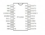
I stumbled on this IC today, PT2258, here is the datasheet . Curious if anyone has used it. Looks to be easily controllable with the picaxe. I ordered a few chips to try.
I doubt it's high fidelity but am hoping to be surprised. If it works well it will be perfect for my application, I'm working on an active crossover for my speakers. The active filter is built but it would be nice to control the volume to each driver from listening position. I have abandoned the purist approach to audio, every recording is different and I find i need to dial in the crossover to taste.
 

hippy

Ex-Staff (retired)
Not used it and couldn't find any other PICAXE users who had but does look usable with a PICAXE. The biggest challenge seems to be figuring exactly what to send but that should mostly be re-ordering what the datasheet shows.

Seems to me it should be pretty easy after that, wait 200ms+ after power-up, an initial $C0 and then a single byte 'mute' or 10dB and 1dB pairs for 'volume', and it looks like those could be packed into a single transmission. Then just pairs to set a particular channel's volume. I'm sure we'll get you going if you do get stuck.
 

julianE

Senior Member
There are arduino libraries for the chip if we need to reverse engineer it. Thank you in advance for all the help, after all these years I still struggle with I2C.
 

julianE

Senior Member
The chips came in after a long wait.
Everything is bread boarded and i ran PhilHornby's 14M2 I2C scanner program. I have both control pins grounded.
The scanner came back with 0x40 for the I2C address and if i change the control pins different I2C address is scanned so I'm fairly sure the comms are working. I do have pullup resistors on the I2C lines.

I have a signal generator putting 1KHz at .6 volts through a capacitor to input 1 and an oscilloscope attached through a capacitor to output 1.
The signal comes out with zero attenuation.

I haven't a clue on how to get the I2C working,
here is what i tried, using 42db example on data sheet.
No change in the output after running my code attempt.

Code:
#picaxe 14M2
pause 500
hi2csetup i2cmaster, 0x40, i2cslow, i2cbyte   
hi2cout (0xC0)

hi2cout(%11010100, %11100010)
Thanks in advance for any advice.
 

julianE

Senior Member
I made some progress, according to the datasheet the address is 80 once i changed it, the attenuator worked.

hi2csetup i2cmaster, 0x80, i2cslow, i2cbyte

I tried different values of attenuation and it's working, now need to get it working for individual channels.
 

hippy

Ex-Staff (retired)
now need to get it working for individual channels.
The ordering of channels is quite bizarre, with no easy way I could see to convert from the number of the channel to what the MSB's of the command for that channel would be -
Code:
0 0 0 | 0 | 0  B2 B1 B0 | Channel No. 3, -10dB/step  011 -> 000
0 0 1 | 0 | 0  B2 B1 B0 | Channel No. 4, -10dB/step  100 -> 001
0 1 0 | 0 | 0  B2 B1 B0 | Channel No. 2, -10dB/step  010 -> 010
0 1 1 | 0 | 0  B2 B1 B0 | Channel No. 5, -10dB/step  101 -> 011
1 0 0 | 0 | 0  B2 B1 B0 | Channel No. 1, -10dB/step  001 -> 100
1 0 1 | 0 | 0  B2 B1 B0 | Channel No. 6, -10dB/step  110 -> 101

0 0 0 | 1 | A3 A2 A1 A0 | Channel No. 3, -1dB/step   As above
0 0 1 | 1 | A3 A2 A1 A0 | Channel No. 4, -1dB/step
0 1 0 | 1 | A3 A2 A1 A0 | Channel No. 2, -1dB/step
0 1 1 | 1 | A3 A2 A1 A0 | Channel No. 5, -1dB/step
1 0 0 | 1 | A3 A2 A1 A0 | Channel No. 1, -1dB/step
1 0 1 | 1 | A3 A2 A1 A0 | Channel No. 6, -1dB/step
My pragmatic solution would be to apply some correction fluid to the datasheet and renumber what the chip calls them. -
Code:
      .---_---.
In 4 -|1    20|- Out 4
In 2 -|2    19|- Out 2
In 0 -|3    18|- Out 0
     -|4    17|-
     -|5    16|-
     -|6    15|-
     -|7    14|-
In 1 -|8    13|- Out 1
In 3 -|9    12|- Out 3
In 5 -|10   11|- Out 5
      `-------'
I think I've got my numbering correct but best to double check it.
 

julianE

Senior Member
My pragmatic solution would be to apply some correction fluid to the datasheet and renumber what the chip calls them. -
Good grief, that's brilliant thinking, I'm genuflecting in your general direction.

i ran tests on individual channels today, channel 1 and channel 2 (in their labeling) and it worked a charm.
before i invest more time i want to check the audio quality, next step will be to volume control a headphone amplifier, easier to discern any audio issues with headsets.
I'm thinking of making pc boards for the volume control portion.
I have to decide how to control the volume chip remotely, do i use, bluetooth, IR, rf modules or over the internet. I'm favoring IR thinking it would have least chance of getting into the audio. Perhaps use a nextion display in a control box.
 

julianE

Senior Member
I tried the volume control chip with audio. It's not bad but certainly needs to be better. There are assorted extraneous sounds, you can hear when the program is being downloaded and other digital sounds. I have everything sharing the same ground on the breadboard. the chip has provisions for two grounds a digital ground and what i guess would be signal ground.

25755


pin 5 is digital ground what SCL and SDA reference to and pin 14 is the analog ground. the chip can take up to 9 volts making it possible to run the picaxe portion at 5V and the PT2258 at up to 9V. Have to do some thinking on how best to keep the digital noise out of the analog section.
Perhaps one of the forum analog design experts will chime in.
In the meanwhile I'll add more capacitors to snub digital noise.
 
Top