I've seen recent posts concerning project boards controlling
relatively high-power outputs.
A genuine question:- what is the current capacity of the tracks?
As an example, the 20M board. (AXE118)
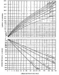
The ULN2803 can easily handle >100mA per output. All outputs on.
http://www.rev-ed.co.uk/docs/ULN2803A.pdf
Page 5. fig 12
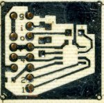
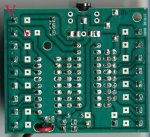
The photo shows the back of my 20M board.
At present, I'm connecting V+ (5V) to the top left (Large V), but testing only
low power LED's.
When I move to the 300mA monster LED's, I'll remove link1 and use the line
of individual connectors. (little v).
Only one or two LED's will be switched at any one time, as per datasheet.
But, can the ground tracks cope?
Or should I make alternative arrangements?
e.
relatively high-power outputs.
A genuine question:- what is the current capacity of the tracks?
As an example, the 20M board. (AXE118)
The ULN2803 can easily handle >100mA per output. All outputs on.
http://www.rev-ed.co.uk/docs/ULN2803A.pdf
Page 5. fig 12
The photo shows the back of my 20M board.
At present, I'm connecting V+ (5V) to the top left (Large V), but testing only
low power LED's.
When I move to the 300mA monster LED's, I'll remove link1 and use the line
of individual connectors. (little v).
Only one or two LED's will be switched at any one time, as per datasheet.
But, can the ground tracks cope?
Or should I make alternative arrangements?
e.
Attachments
-
 63 KB Views: 38
Last edited:
")