Problems with reading/writing to 24C32

wlie

Member
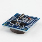
I try to read and write to the 24C32 module in this "Tiny I2C RTC DS1307 AT24C32".
tiny rtc.jpg
According to the seller includes one 32k RAM module. My problem with it is that I apparently can not address more than 256 bytes.
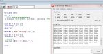
I tested it with this code.
Code:
#PICAXE 08M2
#No_Data

	i2cslave %10100000, i2cfast, i2cword
	pause 50

for w4 = 0 to 4095
	writei2c w4, (17)
	pause 20
next w4

sertxd ("End writing",cr,lf)

for w4 = 0 to 300
	readi2c w4, (w10)
	pause 20
	sertxd (#w4,"=",#w10," ")
next w4
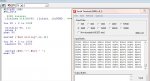
Over address 255 I read incorrect data.
I have investigated the module with a magnifying glass and on the little chip there is written 24C32AN, so it should be able to contain 32768 bits.
What am I doing wrong?

By the way - I have no problem setting and reading the time with I2C commands.
 

nick12ab

Senior Member
What could be a problem is that you're using i2cfast when there is a device on the i2c bus that doesn't support it - the DS1307. If one device on the bus requires i2cslow then you must use i2cslow for all devices on the bus otherwise the DS1307 might mistake the faster data being sent to the EEPROM as its own address and some commands/data and then it might try to send data itself.

Is the WP pin on the EEPROM connected to GND? If not, then the 'upper quadrant' of the memory will be write protected. However if only the first 256 bytes become written with the correct value then that suggests that more than the 'upper quadrant' is write protected.

Also try chaging from the writei2c, readi2c and i2cslave to the newer hi2cout, hi2cin and hi2csetup commands.

There's also the possibility of counterfeit components - have you tried a known genuine EEPROM?
 

wlie

Member
nick12ab
Thanks for your reply

I've tried with both fast and slow. It makes no difference.
WP is connected to ground.
hi2cout, hi2cin and hi2setup does not change anything. By the way what is the difference between writei2c, readi2c and i2cslave commands and the newer commands?
I am fortunate that I have a AXE110 with a 24LC256 module - this I have now loaded with this
Code:
# PICAXE 18m2
# NO_DATA
# Terminal 4800

break 200

hi2csetup i2cmaster,% 10100000, i2cfast, i2cword
break 50

to w9 = 0 to 300
hi2cout w9, (45)
break 20
next w9

to w9 = 0:02 260
hi2cin w9, (w10)
break 20
sertxd (# w9, "=", # w10, "")
next w9
[/ code]
There must be something wrong with the way I try to write and read as the AXE110 shows exactly the same wrong result.
 

wlie

Member
Ups
The program was not the right one, but here it is
Code:
#PICAXE 18M2
#No_Data
#Terminal 4800

pause 200

	hi2csetup i2cmaster, %10100000, i2cfast, i2cword
	pause 50

for w9 = 0 to 300
	hi2cout w9, (45)
	pause 20
next w9

for w9 = 0 to 260
	hi2cin w9, (w10)
	pause 20
	sertxd (#w9,"=",#w10," ")
next w9
 

wlie

Member
From address 0 to 255 the value is 45 (the written value)
from address 256 to 511 the value is 301
from address 512 to 767 the value is 557
from address 768 to 1023 the value is 813
 

wlie

Member
Look there ar exactly 256 between the written value (45) and 301 and also 256 between all the othe values.

Rexlan
What do you mean with: Page frame?
 

RexLan

Senior Member
I had an issue once and found that I was overwriting the page boundary and corrupting the data? However, this does not appear to be the issue if you're getting 256 as an adder to each sequence.

Have you tried actually setting W9 to =0 before you start the read loop?

AT24C32/64, 32K/64K SERIAL EEPROM: The 32K/64K is internally organized as 256
pages of 32 bytes each.
 

nick12ab

Senior Member
Could the reason be that you're reading the data into a word variable? Try doing it with just a byte variable.
 

eclectic

Moderator
I own a very similar module, but the Eeprom is
labelled
ATMEL 24C32N
http://www.atmel.com/Images/doc0336.pdf
Run these two programs, and look at the differences.

Code:
#PICAXE 18M2
#No_Data

 i2cslave %10100000, i2cfast, i2cWORD
 
for W0 = 0 to 1000

 writei2c W0, (1)
 pause 5
next W0

sertxd ("End writing",cr,lf)

for W0 = 0 to 1000
 readi2c W0, (b10)


 sertxd (#W0,"=",#b10," ")
next W0


#rem

#PICAXE 18M2

#No_Data
; byte ****************
 i2cslave %10100000, i2cfast, i2cbyte

 
for W0 = 0 to 260
 writei2c W0, (1)
 pause 5
next W0

sertxd ("End writing",cr,lf)

for W0 = 0 to 260
 readi2c W0, (b10)

 ;pause 5
 sertxd (#W0,"=",#b10," ")


next

e
 

westaust55

Moderator
The 24C32 has an 8 byte page size. Sending one byte at a time will never be a problem with paging.
The issue with paging arises when sending multiple bytes and subsequent bytes would cross a page boundary - ie going past bytes 7, 15, 23, 31, etc.

What supply voltage are you using? The min voltage for the DS1307 and the 24C32 are both 4.5 volts.

Write cycle time from the datasheet is 5 ms, so there is no need for pauses of 20 or so.
5 as per eclectic's code examples will suffice at a clock speed of 4MHz

Reading into a word variable will not cause a problem. The byte from the read data is placed in the lower byte of the word variable and I believe the upper byte cleared.
This topic has been raised before and Technical has advised generally as above.
That said, if you look at the values you are getting back, the low byte in the receiving word is always the same = 45 = $2D
but the upper byte is being loaded is incrementing at each "block" so first block has upper byte = -, second block has upper byte as 1, third block has upper byte as 2, etc.
As nich12ab suggests using a byte variable to read in the data will overcome the problem
 
Last edited:

wlie

Member
eclectic solved the problem.
Two things I learned.
First You need ic2word (not ic2byte) in command i2cslave% 10100000, i2cfast, i2cword
Second When you read you have to read the data into a byte varable and not as I did in a word varable (as westaus55 also suggested)
Thanks to all for your kind suggestions.
 

westaust55

Moderator
From a few tests I have done the observations are:

If a word variable is used to receive the byte read in from the EEPROM the results are:
1. the PE in simulation mode clears the upper byte - (I tested this by pre-loading another value into the upper byte before an EEPROM read)
2. the firmware in actual PICAXE chips (08M2, 18M2+ and 40X1) writes a value into the upper byte equal to the "block number" where blocks are 256 bytes each

So PE Simulator and chips are not consistent with handling of the upper byte but then we should only be reading into a byte variable.
 

nick12ab

Senior Member
Don't forget that the page for the hi2csetup command states the slave address, speed and whether it uses i2cword or i2cbyte.

However after recent discussions regarding M2 parts and table, I wouldn't rely on the command pages at the moment and would Google the datasheet for the IC to check these details.
 

westaust55

Moderator
The EEPROM in question is a 24C32 which is an obsolete part replaced by the 24LC32A
They are not covered in the PICAXE manuals or online Command pages so as with any chip the datasheet should be downloaded as nick12ab suggests to verify pertinent data such as max clock speed, min operating voltage and key timing requirements, paging size, etc.
 

wlie

Member
I checked again with my magnifying glass. It turns out that it is 24C32AN.

Another thing is that the clock is very inaccurate. I bought 2 module and one module is 30 seconds too fast on one day and another loses 16 seconds a day. I think I can make a watch just as accurate with only a PICAXE.
They were cheap and you get what you pay for.
 

nick12ab

Senior Member
Another thing is that the clock is very inaccurate. I bought 2 module and one module is 30 seconds too fast on one day and another loses 16 seconds a day. I think I can make a watch just as accurate with only a PICAXE.
That is bad to have an inaccuracy of over 1 second per hour! My legit DS1307s and crystals are inaccurate by about 1 second per day.

Have you got any known non-counterfeit DS1307s and crystals? Try using the crystals from the boards with a known good DS1307 and also try using known good crystals with the DS1307s on the boards.

It's likely that the pennypinching seller bought factory reject crystals at a reduced price, but then again it's also likely that the ICs are counterfeit too.

I checked again with my magnifying glass. It turns out that it is 24C32AN.
The datasheet page 13 states that the AN extension means that it's a 0.15" wide SOIC IC, and not that it's a completely different type of EEPROM.
 

AllyCat

Senior Member
Hi,

Yes that does seem rather poor for a "Watch" crystal, but perhaps you can trim it with a small capacitor?

I think I can make a watch just as accurate with only a PICAXE.
The PICaxe clock is only specified to about +/- 1% which represents 15 minutes per day. You can trim it slightly with calibfreq but I doubt if you'd better 1 min/day unless the temperature is extremely constant. I believe that hippy has used an external watch crystal with an 08M2, but the pinout (and power consumption/management) was not very favourable compared with a dedicated RTC.

Cheers, Alan.
 

westaust55

Moderator
Keep in mind that these modules as per the image in post 1 are pre-assembled with the RTC, crystal and EEPROM.
Wlie is unlikely to know much more than whether the module was bought via E-bay, or some reputable source.

A possibility is that the wrong crystal has been fitted. A crystal having a specified load capacitance (CL) of 12.5pF.
Some other Dallas/Maxim RTC chips use a 6pF crystal. Having the wrong one does make a fair difference in timing accuracy.
I recall a past thread on this forum where swapping out a crystal made a the RTC far more accurate.
 
Top