Problem with programming with Sharp GP2D12

Jon__

New Member
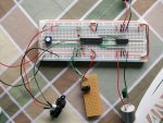
My circuit has a Sharp GP2D12 sensor plugged into it, in order to program the picaxe 28X1 i have to remove the sensor from the power lines before the downloading will actually start, else it gives me a memory verification failed message. This sensor and two LEDs are the only two things i am currently running on the board, the chip also has a l293d plugged into the power lines and connected to picaxe but not currently used - all pins are set to low to stop floating input/outputs.

Does anyone know why i have to keep removing the sensor, it is getting a tad annoying now?
 

BeanieBots

Moderator
Well, you shouldn't need to remove it.
The most common cause of verification error is a power supply problem.
If your supply is weak, then removing the sensor might be just enough to bring it back to a working value again.
Alternatively, there might even be more fundamental wiring problem which is causing parasitic powering via the sensor output. This can happen if the sensor power is different to the PICAXE power or even if the power connection to the PICAXE is missing altogether.

Double check your circuit and power supply.

"all pins are set to low to stop floating input/outputs"

ALL pins? Including the sensor input? How have you done that?
Floating outputs? They can't!
 

westaust55

Moderator
Problem with programming with Sharp GP2D12 connected

Which Rev Ed start/proto board or other board are youy using?

Suggest that you upload your circuit diagram showing how you have the Analogue IR sensor and the other devices connected.
 
Last edited:

Jon__

New Member
I have uploaded my circuit diagram, i can't see anything wrong with it myself but maybe i don't know some crucial information.

The motors are not currently used as i am trying to get the sensors working, however, i am aware they might become a nightmare very quickly with one power supply.
 

Attachments

bgrabowski

Senior Member
You didn't mention the switch which appears to be connected to leg 2. What is that for and is it working as you expect?
 

Dippy

Moderator
You don't mention what your power supply is.....????
Or how good it is.....
The power supply is important.

Can you scope your power supply as you download?

Have you tried, say, 22uF cap across PICAXE power pins right next to chip. You have the space.
You may also need 47nF to 100nF ceramic across the pins too when you get your motor going.
This could be important with all those wires (antennas) all over the place.

Also, is the download circuit correct on your breadboard?
Your 10K res (to ground) looks like it's on the 'wrong side' of the 22K??
The 10K to ground should be on the PC connector side of the 22K res.
 

hippy

Ex-Staff (retired)
The breadboard circuit looks okay. Maybe try and isolate exactly what causes the problem. Does leaving the GP2D12 connected and disconnecting the motor driver chip let it work, what about disconnecting just the GP2D12 Vo wire or just the GP2D12 Vcc wire.

What voltages does a Programming Editor Serial Port Test give on PICAXE leg 6 to 0V with and without the GP2D12 ?

What are you using as a power supply ? If batteries, have you tried new ones ? What voltages do you get when downloading and not ?

Have you tried adding decopling capacitors across +V and 0V ?

Are the verification errors at specific addresses, near each other, during particular phases of downloads ( code, table, data ) ?

The GP2D12 can draw up to 50mA, the PICAXE can draw a fair bit when programming Flash or Data Eeprom ( couldn't find a figure in the data sheets - I recall I've seen my PSU indicator jump up to ~30mA at times ) so that's a loading which could pull a weak supply down.
 

BeanieBots

Moderator
Agree with Dippy.
Looks like a 22k/10k potential divider and NOT the download circuit.
That would certainly account for verification errors.
 

hippy

Ex-Staff (retired)
Download Interface

Also, is the download circuit correct on your breadboard?
Your 10K res (to ground) looks like it's on the 'wrong side' of the 22K??
Dang, I looked at that and still missed it :)

Yes, the 10K seems to be on the wrong side of the 22K. Check the PICAXE manuals. This is not intended as a potential divider, the 22K is for current limiting, the 10K only to stop the line from floating when the download cable is disconnected.
 

Dippy

Moderator
I thought for a moment I was going to be sent back to my Nursing Home :)

PS. As a slight aside Jon, I assume you've read the Data Sheet where it suggests a 10uF (or higher) capacitor right next to the device power pins for stability? I couldn't quite see it in your picture. It's probably behind it where I can't see it.
 
Last edited:

Jon__

New Member
oops, i forgot all about the switch - but yes it does work.

Good spot about the download circuit, i have corrected it and it still doesn't download with the sensor plugged in. I have tried removing the Vo but that makes no differnce, you have to remove Vcc. I will try removing the driver chip in a second.

Where abouts does it say it needs a 10uf cap on the power pins, i don't think i have seen that part of the datasheet? Is that across pins 19 & 20?

The power supply is a 3x brand new AA batteries (Duracell Plus).

Sorry for any obvious mistakes i am making but this is only my 3rd project with picaxe and i am finding different datasheets tell you different things.
 

Dippy

Moderator
Have you tried measuring the voltage at the actual PICAXE power pins when everything connected?

Well worth a double check with a multimeter. A resistive (e.g. dirty or loose) connection could affect things.

If I were doing this I would tediously be checking the quality of continuity for ALL the wiring with a multimeter.
Sometimes something really basic can give you a "Doh!" moment.

Re: Capacitor for the GP2D12
There are several variants of this device - and several varieties of Data Sheet.
Some mention it, some don't.
I don't know how important the capacitor is, but as it gets a mention then it can't hurt to include it.

http://www.farnell.com/datasheets/62635.pdf
Page 8 Para 7-8


http://www.farnell.com/datasheets/62636.pdf
Page 3 para 7-8

Two other Data Sheets I looked at didn't mention it.

Capacitor goes across the GP2D12 power pins, and it implies you puit this capacitor as close as practically possible to the GP2D12.
I'm not suggesting this will cure the problem, just that it may need it for best performance once you have it up and running.

I also see from the 4 varieties that i have looked at that Sharp recommend 4.5 to 5.5V operation.
I think 3 AAs will be too feeble for prolonged oepration, though should be OK for brief testing - assuming you batteries are OK.

I would certainly disconnect the other bits 'n' pieces while you get this bit sorted.
I've seen numerous examples people going head-first into a monster breadboard and then wrestling with a problem. Always build up in stages - even the Big Boys do that.

An option at a later stage would be to have the PICAXE being able to power-up the Sharp so you can use it when you wnat to and not waste power. I'll leave that for others to tell you how.
 

Jon__

New Member
Thanks for noticing that in the datasheet, has saved my copious amounts of time.I don't really have any capacitors that big in my colletction, i used to do a lot of tuning circuits which required small capacitors, so i have had to stick a 100uf in there for now. The downloading works again now and the sensor seems happy.

Thanks guys that has really cheered me up.

Now i want to get the motors working but i fear this might course more problems without smoothing capacitors. Looking at my circuit does anyone have any suggestion of where could be problem areas, i will have a test with them and see what happens. I think the picaxe might need something on its powe rails though?

Saying this it seems to work ok without a problem, now i need to extend with IR controller, does anybody now if using an IR diode will effect the IR sensor?
 
Last edited:

Dippy

Moderator
"I think the picaxe might need something on its powe rails though?"
- see post 6.

There are usually issues when you get motors invloved.
People have favourite things. Caps across motor terminals... extra decoupling to PICAXE. Separated power supplies for PICAXE & Motor. etc.
All sorts of tricks and black magic.
A good manly power supply is a start.
PCB physical layout is often very important and often ignored.

Did you post a circuit diagram?
A circuit diagram being a drawn schematic....

Happy New Year and all the Best.
 
Top