Hairy Animal
Member
I'm playing with a little project to open a door under manual or timed control using an 08M2 for the main control and an AXE133 board with a simple 2 x 16 LCD to show what's happening. The 08M2 doesn't have quite enough I/Os by the time I've used two (SCL & SDA) for the RTC, one for the serial out to the display, another for the servo and two for push buttons.
This is because I want to use a USB Power Bank as the PSU. These things come in a variety of capacities and at supermarket prices are a very cheap way of getting a high capacity 5V power source. They have one disadvantage though, if supplying only a few mA they switch off after about 30 seconds.
To get around this while still using as little average current as possible I've found that if I pulse about 500mA for a few tens of milliseconds every 20 seconds, it keeps the Power Bank turned on.
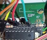
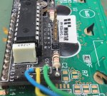
Unfortunately I've used all the I/Os on the 08M2 but, there are three unused outputs on the nicely designed AXE133 board (see pic) and the standard REV ED software conveniently shows how to use them:
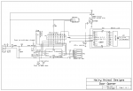
So I thought it wouldn't be too difficult to use one of these outputs to pulse the current as required, but it doesn't seem to work as I'd expect. After various experiments I got rid of all my other code and just tried to switch the relevant output on and off with an LED to show what's happening (see circuit diagram).
Note: the code is using C.1 as is the actual circuit where the schematic shows C.2. I've tried both with the same results.
What actually happens after power up is:
Note that although writing "010" nominally to the C.2, C.1 & C.0 pins, the C.2 & C.0 pins never go high, so it's not as simple as the inverse of what's been written to that port.
Can anyone help please?
This is because I want to use a USB Power Bank as the PSU. These things come in a variety of capacities and at supermarket prices are a very cheap way of getting a high capacity 5V power source. They have one disadvantage though, if supplying only a few mA they switch off after about 30 seconds.
To get around this while still using as little average current as possible I've found that if I pulse about 500mA for a few tens of milliseconds every 20 seconds, it keeps the Power Bank turned on.
Unfortunately I've used all the I/Os on the 08M2 but, there are three unused outputs on the nicely designed AXE133 board (see pic) and the standard REV ED software conveniently shows how to use them:
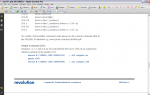
Code:
; 255, X    control outputs C.2, C.1, C.0 (via lower 3 bits of X)
;        So, if using a backlit LCD with the active low transistor driver
;        on output C.2, then 255,%000 switches backlight on and 255,%100 switches off
Code:
; Display tester.
#picaxe 08M2
; 82/2048 bytes
#NO_DATA
;
; Outputs
; C.4 - serial line to LCD (AXE133 board with 18M2 & 16 chr x 2-line display).
;
; Three outputs also available on the 18M2+ (LCD board):
; 255, X    control outputs C.2, C.1, C.0 (via lower 3 bits of X)
; So, if using a backlit LCD with the active low transistor driver
; on output C.2, then 255,%000 switches backlight on and 255,%100 switches off
; C.2 has an 11.5 R load to be pulsed on briefly to keep the 5V USB Power Bank
; alive, otherwise it turns off because the circuit uses too little current.
;
init:
;
PAUSE 2000
SEROUT c.4,N2400,(254,1)      ; Clear display
PAUSE 100
main:
    SEROUT c.4,N2400,(255,%010)             ; Turn on LED
    PAUSE 100
    SEROUT c.4,N2400,(254,128)
    ; Move to start of first line.
    SEROUT c.4,N2400,("LED on")
    PAUSE 5000
    SEROUT c.4,N2400,(255,%000)           ; Turn off LED
    PAUSE 100
    SEROUT c.4,N2400,(254,128)
    ; Move to start of first line.
    SEROUT c.4,N2400,("LED off")
    PAUSE 5000
    SEROUT c.4,N2400,(254,1)      ; Clear display
    PAUSE 1000
;
GOTO main
;~~~~~~~~~~~~~~~~~~~~~~~~~~~~~~~~~~~~~~~~~~~~~~~~~~~~~~What actually happens after power up is:
- Welcome display shows
- Screen clears
- "LED on" message appears, LED stays off.
- "LED off" message appended to the "LED on" on the top line (i.e. the SEROUT c.4,N2400,(254,128) is ignored, and the LED turns on.
- The screen clears again and the LED turns off with the "LED on" message appearing again.
Note that although writing "010" nominally to the C.2, C.1 & C.0 pins, the C.2 & C.0 pins never go high, so it's not as simple as the inverse of what's been written to that port.
Can anyone help please?
")