Powering off an 08M under software control

Tom2000

Senior Member
Tom,
Agree that the regulator with on/off is simple and elegant when you need a regulator but many have been asking for the 1 transistor circuit for battery operated systems - i.e. no regulator.
In that case, I'll vote for a low-side transistor. For a BJT, drive the base hi-low. For something like a 2N7000, drive the gate out hi/input off.

But I really like the regulator method.

Tom
 

Dippy

Moderator
Hi Tom,
I think you'll find you have misread.

The Max.5uA is really a MaxDOT as in abbreviaton of Maximum
Next page shows Max OFF current as 5uA.

Max. = Maximum like No. = Number.

If you read further you'll see in the line above the one you mention "Max. 8mA", then in the real data on the next page you'll see "8mA" for that parameter.

Don't want to be picky really :) but it does prove that I look at your links.

BCJ: Of course I realise you wanted to see if it worked. And it did as you have shown. Good. Though I'd be surpised if a m'chip app circuit didn't. I was just wanting to compare the benefits over 2 transistor, which I honestly cannot see. Firing a charge pump must surely use more current than a FET/FET or BJT/FET arrangement and be a marginally more noisy circuit as well.

Anyway, like I say, there's enough info to take yer pick now. Personally, I'll stick to a coupla smd FETs. I'll leave you all to it.
 

BCJKiwi

Senior Member
Just carried out a few current checks without the LED;

Total current into the PICAXE with no outputs connected is ~730uA

Total current with Microchip circuit (i.e. charge pump, mosfet etc) connected is ~780uA - an additional 50uA.

Total current into the mosfet gate circuit which includes the gate current and the gate discharge resistor current is ~43uA. This is with a 100k gate discharge resistor. This current could be reduced slightly with a higher value resistor.

So the charge pump itself is only consuming 7uA.

If I understand this correctly this is because a mosfet does not really consume power through the gate circuit, it just needs the voltage on the gate to be maintained.

A total of 50uA isn't much for the function.
 

wilf_nv

Senior Member
single high side 2N7000 circuit with charge pump

A commonly available N-ch MOSFET such as the 2N7000 requires about 3V between the gate and the source to turn on. If the MOSFET used as a source follower with the MOSFET drain pin connected to a 5V rail to be switched via the MOSFET source pin to the 08M Vdd pin under software control, the simple charge pump circuit shown can be used to raise the MOSFET gate drive voltage to more than 8V and solidly switch +5V to the 08M Vdd pin. The advantage is that only a few tens of microamps of gate drive current are consumed. The disadvantage is that the 08M output must oscillate to drive the charge pump circuit. The PWM pin, if available, can be used for this or any other output pin can be periodically toggled low,high,low,high to refresh the gate voltage at least once every 100ms. When 08M output pin oscillation stops, the MOSFET turns off a few hundred milliseconds later. With the MOSFET in the OFF state, the 08M standby current is a reduced to a few nanoamps.
 

Attachments

killerwhat

New Member
Cosmic Software.

It's been done before and posted. Attached circuit is Push-On/Push-Off/Program-Off.
Works every time. Zero power when off. No leakage paths. The big challange seems to be to do it with one transistor, mosfet, or small IC. :D

Ken
Hello Ken & all
I am a relative newbie but have used simple picaxe circuits in my design technology teaching over the years.
Currently I have a student project "bike safety light" that uses an 08M to run 20 repeats of 3 different sequences of 4 leds until the circuit is switched off. I want to develop it to work more like the commercial products that use a momentary switch to start it, cycle through some different flash patterns and turn it off. Can the suggested solutions contained in this thread provide me with a method? At the moment the component count is very low and I don't want to end up with something that 13 year olds can't make reliably if I can help it.
Looking forward to hearing from you or anyone that can contribute. All the best, Steve.
 

AllyCat

Senior Member
Hi Steve,

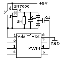
Welcome to the forum. It might not be a good idea to try to follow up such an old (7 years) thread. I don't know if Ken is still active on the forum, and you are making an (IMHO incorrect) assumption that the method is appropriate for your project. Also, other members (and me) are not likely to want to plough through 44 previous posts concerning arguably "obsolete" components. The 08M has been superceded by the 08M2 and there are now "Logic Level" FETs available, which make the charge pump in the previous post generally unnecessary.

So what are your (or the project) requirements? In particular, what is the battery supply (voltage), how many and what specification are the LEDs, and must you use an 08M or can you use an 08M2? A diagram of your present circuit could be helpful.

However, IMHO all that the circuit probably needs is a Battery, PICaxe, LED(s), push-button, a cheap bipolar transistor (e.g. BC548 or BC337, etc.), a few resistors and, of course, a supply decoupling capacitor! But beware that a "toggle" acting pushbutton switch can be a programming challenge because of "contact bounce". An additional capacitor (across the pushbutton) might be a worthwhile addition. The PICaxe's SLEEP or NAP commands should be able to handle the low power requirement when "Off".

Cheers, Alan.
 

killerwhat

New Member
Hello Alan, thank you so much for your reply. Do you think I should start a new thread or shall we carry on here?
Any how, we are in fact using an 08M2. The original schematic and PCB was drawn in pcb wizard, I will post the diagram when back at work on Monday. Once again thank you for responding. Best regards steve.
 

AllyCat

Senior Member
Hi Steve,

IMHO it probably would be better to start a new thread. You can link to this thread to show that you've done some "research". The main advantage of using an old thread is that it may notify some of the original contributors, but that should have happened by now anyway. Others may consider that a thread of nearly 50 posts that hasn't reached a "conclusion" is best avoided. :)

This is quite an interesting thread, but I don't think the OP ever explained what his load (power) was, or what "off" power consonsumption he considered acceptable, so it rather wandered off topic. FYI a basic PICaxe requires about 0.5 mA which can drop to a few uA in sleep/nap. Somewhere on this forum there is a thread about a PICaxe which has been flashing a LED for many years from the same battery!

Cheers, Alan.
 

killerwhat

New Member
Hi Alan
OK, I'll start a new thread.
How do I link to this one?

Here is the schematic and the PCB layout:
cycle light diags.jpg

Cheers, Steve
 

AllyCat

Senior Member
Hi Steve,

The way I do it is to copy the address of the required thread/page from the browser and paste it between [ url ] and [ /url ] tags (no spaces, I added them to make the tags inactive here). Or a more elegant form is:
[ url = addresslink ] displayed text [ /url ] . You can do a Preview to check before posting.

Nice diagram, but there should be a decoupling capacitor (maybe 100nF and/or 10 uF) across the PICaxe pins 1 and 8, and I'd prefer to see 2 or 3 x AA(A) cells instead of thrashing a poor CR2032. They're really intended for (very) low drain applications.

Also, if it's a "momentary contact" pushbutton switch (to change modes), I'd expect it to be on Leg 4 (with other switch contact to ground) with Leg 1 directly to the battery +.

Cheers, Alan.
 
Top