Pin States

alband

Senior Member
Hi,

The title is to make searching easier. My main question is regarding using a particular relay with a PICAXE, but I also have a general question about the states of I/O which is a far more useful piece of knowledge than specific information on a random component.

I'll start with the title question. As I understand, a PICAXE (or other uController) I/O can have three states: Input, Low and High. "Input" is a high impedance state, whereas "Low" means the pin is effectively tied to ground? So if I have a relay coil I want to trigger both ways, one pole of the coil should be "high" the other "low". Yes? Or should it be "high" and "input"? I suspect the former, is there anywhere in the manual this is explained or a particular term(s) I can google.

2nd question: According to the manual, each pin can source/sink 20mA, and all pins 90mA. According to the datasheet for the 28X2:

Input clamp current, IIK (VI < 0 or VI > VDD)..........................................................................................................20 mA
Output clamp current, IOK (VO < 0 or VO > VDD) ..........................................................................................................20 mA
Maximum output current sunk by any I/O pin..........................................................................................................25 mA
Maximum output current sourced by any I/O pin ....................................................................................................25 mA
Maximum current sunk by&#61472;all ports (-40°C to +85°C)........................................................................................... 200 mA
Maximum current sunk by&#61472;all ports (+85°C to +125°C)......................................................................................... 110 mA
Maximum current sourced by all ports (-40°C to +85°C) ......................................................................................185 mA
Maximum current sourced by all ports (+85°C to +125°C) .....................................................................................70 mA
Which of those figures is the corresponding figure to the manual? Only 5mA in it I know, but I want to use a relay that has a coil current of 33mA (+-10%), so I need all I can get. Obviously, 33mA > 25mA, but it's a latching relay so only requires a pulse of current. I'm not quite sure what the datasheet is saying on the pulse length (top of "Characteristics" table on p2), but the figures are around 3ms. So the question is, could I have a PICAXE source and sink a current of 36.3mA (110%) for around 3ms?

I could use a different relay or a transistor to drive it. However, I have limmited space so the fewer components the better. That relay is small, so good, but it is also latching and has a coil voltage which my 3.3V (as per the requirements of the app) 28x2 can provide.

Thanks in advance as usual,

David.
 

premelec

Senior Member
I'd stick in a transistor - and catch diode... there are very small transistors these days... you could also see if the relay will work ok on less current and put a resistor in series with it's coil... 20 ma is about max you can use reliably... You can use a series resistor in parallel with series capacitor to give it a kick but then you are complicating beyond just using a small transistor driver... :)
 
Last edited:

westaust55

Moderator
The pin ratings that you reference are the ABSOLUTE MAXIMUM ratings that should never be exceeded.

Note also the warning note at the bottom of that page:
&#8224; NOTICE: Stresses above those listed under &#8220;Absolute Maximum Ratings&#8221; may cause permanent damage to the
device. This is a stress rating only and functional operation of the device at those or any other conditions above those
indicated in the operation listings of this specification is not implied. Exposure to maximum rating conditions for
extended periods may affect device reliability.
It is generally recommended that the current into (sink) or out of (source) an IO pin should be limited to 20 mA for normally operating purposes.

Consider using a transistor interface between the PICAXE and relay (with freewheeling diode) as shown in PICAXE manual 3 page 8.
 

srnet

Senior Member
There is actually 2 input states, digital and analogue.

And another output state, the DAC level.

Then there is the pin state for the resonator pins.
 

hippy

Ex-Staff (retired)
There is actually 2 input states, digital and analogue.

And another output state, the DAC level.
Capacitive sensing "touch" inputs could also be considered another input state, and some outputs operate as open-collector / open-drain for specific functions, for example I2C.
 

BeanieBots

Moderator
... but I want to use a relay that has a coil current of 33mA (+-10%), so I need all I can get. Obviously, 33mA > 25mA, but it's a latching relay so only requires a pulse of current. I'm not quite sure what the datasheet is saying on the pulse length (top of "Characteristics" table on p2), but the figures are around 3ms. So the question is, could I have a PICAXE source and sink a current of 36.3mA (110%) for around 3ms?
Hi David.
A sheet of glass can cope with a certain force before it breaks. If you hit it with a higher force for only a short time (eg with a hammer) what happens?
Electronic components have a maximum rating that must not be exceeded, end of.
Running CLOSE to maximum ratings reduces life expectancy.
In addition to that, an output such as a PICAXE output often can't actually supply much more than their maximum output current even when driven into a dead short, so it is unlikely that even if it survived that it could supply the current required for your relay.
 

alband

Senior Member
Thanks for all the replies everyone. I'm getting the feeling >20mA is... bad? ;)
Think I need to exmplain the app generally a bit. The thing the relay is switching is different "loops" into and out of audio signals. It is also inside my guitar, hence the space constraint. This also means there is a battery constraint (elegant + clever solutions preferable to power cord). Because of the power supply being finite, I would want to use latching relays so current isn't constantly drawn in a ON/OFF state. But this means each relay needs to pins for the coil, so that would mean two transistors for each relay. Given there could be about 6 relays needed, it gets difficult.

Still, I can't think of a better solution than using transistors, I agree they are very small these days and it could be done using them. However, can anyone think of a better way of switching an audio signal using a PICAXE? No worries if not, just don't want to miss a trick.

Re the pin states: Looks like I was more than a bit off with my presumption of the number of pin states but it's all good to know. Still, what states would I be looking for to go on either side of a relay coil?

Thanks again for the replies, invaluable resource.

David.

Nice metaphor btw BB
 

alband

Senior Member
Sorry, doubt it. Unless I missunderstood the description. I need something that works just like a relay or a switch. The audio circuit works at voltages up to about 9V but crucially it can't have any "foreign" circuitry introduced in it else it won't sound the same/work. I'll probably manage to fit all the relays etc in, pretty good at cramming things onto a board, just makes it more complicated and inherrantly more problematic.

It's a shame a compact/cheap version of a normal mechanical relay doesn't seem to exist. There would be such a demand for them in the music industry, surely? On that train of thought, what do the music industry use for high quality audio signal switching? For example: something like this is effectively a load of relays, inserting various "loops" into the main line. So what makes them so expensive (there's a reason the price is not on the page that advertises that thing)? There's high build-quality and a sturdy encloser, sure, but that doesn't cost THAT much. Is there more to the circuitry in order to get a nice switch, or is the price tag that high just 'coz it can be?

David
 

srnet

Senior Member
Sorry, doubt it. Unless I missunderstood the description. I need something that works just like a relay or a switch. The audio circuit works at voltages up to about 9V but crucially it can't have any "foreign" circuitry introduced in it else it won't sound the same/work. I'll probably manage to fit all the relays etc in, pretty good at cramming things onto a board, just makes it more complicated and inherrantly more problematic.
Have you done any research on my suggestion, for instance;

http://www.maxim-ic.com/products/switches/

My PC sound card allows me to mix, turn on\off various audio sources, and last time I looked there was not a relay to be seen.
 

Dippy

Moderator
Allband, check the chips westy has suggested..
There are chips SPECIFICALLY for low distortion analogue signal switching - albeit with limited voltage specs.

"The audio circuit works at voltages up to about 9V..."
Perhaps you should clarify.
e.g. +/-4.5V audio frequency? Approx impedence/currents involved?

If it's <+/- 4.5V signal audio then check the chips Westy listed.

"it can't have any "foreign" circuitry introduced"
- what do you mean?
Every modern audio device will have a pile of semiconductors 'in the way'.
It's up to the designer to ensure minimal distortions/losses and good performance using appropriate circuit and component choice.
 

alband

Senior Member
Hi,

srnet: didn't mean to just poo-poo your idea. I checked the link you gave and it said the switching element was controlled by a MOSFET which I don't think is what I need, though I'm perfectly willing to have my mind changed.

More info on the app:

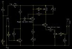
I've got a "Fuzz Factory" effect pedal, which is very much an analog beast, with I'm sure a very tightly designed circuit to make it sound just as it does. I REALLY don't want to affect how it sounds at all. I've got a circuit diagram which I'll attach. I normally wouldn't want to do this but the manufacturer has recently gone open source, so I see no reason why not. The pedal runs straight off the guitar's signal and is powered by a 9v supply. The guitar's output, could surely reach any level depending how hard it's hit? For the moment though, I've been assuming 9V (or a bit more as the battery is rated 9.6v against ground) is what I'll need to be able to cope with. The pedal has 5 POTs to control it and one true bypass DPDT. I want to control these POTs and switch digitally. I'm planning on replacing the physical POTs with digipots but I want to be able to switch back to physical POTs for 2 out of the 5. The components I need therefore have three different roles:
1: to switch the Fuzz Factory pedal on and off. By this I mean "true bypass" circuitry.
2: to switch between two of the digipots and their real POT counterparts. Again, this is very much like a true bypass switch.
3: there is a hack to be done on this pedal to make it more bassy by replacing one of the capacitors with a higher value. I figure if I add some capacitors with sizes like 1,2,4,8,16 etc I can add as much capacitance and therefore as much bass as I want. This switch only needs to "add" a loop, without taking the current loop out, unlike the above. I found a multiplexer under digikey's "Analog Switches, Multiplexers, Demultiplexers" section which would give me 16bit resolution for this, more than enough but I still have my concerns...

By no foreign circuitry, I mean I don't want to add any circuitry to the effects pedal. Idealy, I just want to switch the various components in and out as if I were plugging and unplugging wires on a breadboard. I'm very conserned that adding something with and "on resistance" (albeit, agreably very close the the on resistance of a wire) or something that doesn't seem to be completely electrically isolated to the switching mechanism (FET's aren't completely isolated are they?) will affect the tone of the signal.

I have to dash and haven't read through this so I'll just post what I have for now to make use of time.

Thanks for all the input though, it's much appriciated. I've checked (briefly only though) all the links you've posted. The maxim stuff doesn't seem to go above 5V. Btw the PICAXE would be running on 3.3V. The datasheet you linked westy also seemed to have power supply restraints that wouldn't work. Only had time to glance at it though and haven't had time to search your other suggestions yet.

Thanks again for all the help,

David.
 

Dippy

Moderator
I'm lost. 16bit resolution for an analogue switch... can you give us a link please.

"I figure if I add some capacitors with sizes like 1,2,4,8,16 etc "
- eh?

"The guitar's output, could surely reach any level depending how hard it's hit?"
- eh?
I'm no musician, but I'm sure there's a limit :)

Never assume - as an old Boss once said to me; "Assume can make an 'Ass' out of 'u' and 'me'".
Yes, a vomit inducing phrase, sadly its true.

And you say all that about levels and then mention digital pots.... don't they have a limit? (yes).

Once you read all that properly then you may hopefully have your "mind changed".
Check data sheets for isolation, distortion and voltage handling.
And if your signal path is high(ish) impedance then a hundred ohms will make b-all difference.
I think you need to do a bit more reading about components rather than quick hacking ;)

I wish you good luck with the project as it sounds fun, but maybe you would be happier with mechanical relays.
 

alband

Senior Member
Sorry, forgot to attach the schematic which is on the computer back home. This can do for now. It's fairly accurate but doesn't have as much information on which POTs and capacitors I intend to switch.
http://solgrind.files.wordpress.com/2008/02/zvex-fuzzfactory-rev1-1.gif
 

srnet

Senior Member
So as expected a couple of germanium transistors creating distortion (fuzz).

And your worried that analogue switches will distort the sound ?
 

hippy

Ex-Staff (retired)
srnet: didn't mean to just poo-poo your idea. I checked the link you gave and it said the switching element was controlled by a MOSFET which I don't think is what I need, though I'm perfectly willing to have my mind changed.

I've checked (briefly only though) all the links you've posted. The maxim stuff doesn't seem to go above 5V.
You need to separate the "control" side of things from what it allows by way of "signalling", "switching" or "pass-through".

A device may only be rated for being powered from 5V and use any manner of input type but that is different to what it can switch, for example a 5V relay drawing 10mA through the coils can be capable of switching 250V at 10A.

Most modern audio equipment will use analogue switches like those suggested rather than relays, the type used will determine the quality of signal pass-through. Where a switch can only pass certain analogue voltages the audio signal will have to be reduced in level and amplified afterwards, and the power rail voltages of the device may have to reflect the analogue signal being used. The quality of that circuit dictates the quality of signal pass-through.

You can use relays, and that's perhaps easy because they are simply mechanical switches albeit electrically activated. But don't forget a relay is a bit of "foreign circuitry" too in the signal path, will have resistances and other affects on the signal.

Anything added in a signal path likely affects it, even a jack-to-jack cable, so it's usually not about is it affected but by how much and is that even noticeable to the ear.

Manufacturers use analogue switches because they are cheaper than relays, are often as simple to use, draw less current, and what affect they have on the signal isn't noticeable by most people.

If looking to switch effects pedals there a particular type of analogue switch which is well worth looking at; the "cross-point switch". That's effectively a relay matrix allowing an electrically controlled patch panel. Not always cheap but not the cost nor size of an equivalent 'telephone exchange relay rack' needing a hefty power supply to run it.

The pedal runs straight off the guitar's signal and is powered by a 9v supply. The guitar's output, could surely reach any level depending how hard it's hit? For the moment though, I've been assuming 9V (or a bit more as the battery is rated 9.6v against ground) is what I'll need to be able to cope with.
Likewise, the voltage a pedal operates off will be completely separate to the audio signal levels being passed. It's unlikely any common audio equipment will put out 9V, more likely 1V peak-to-peak or less.
 

srnet

Senior Member
The maxim stuff doesn't seem to go above 5V. Btw the PICAXE would be running on 3.3V.
"The MAX14759/MAX14761/MAX14763 analog switches are capable of passing bipolar signals that are beyond their supply rails. These devices operate from a single +3.0V to +5.5V supply and support signals in the -25V to +25V range."

"The MAX14759 features 1&#937; (max) on-resistance with a ±200nA (max) on-leakage current"
 

alband

Senior Member
Ok, I'll reply chronologically:

Dippy: I jumped a few steps. I should have said "I would get 16bit resolution using a 1:16 multiplexer analog chip, if I had 16 different values of capacitor on each pin, of values, say 1nF 2nF 4nF 8nF 16nF etc". Turns out I was wrong anyway because a multiplecer only connects one at once. Should still work using "n" capcitors with "n" times SPST switches, whatever form the switches take.

The guitar's output is from a coil, so theoretically, has no limit. However, it's probably safe to assume (yep) that the highest voltage any component would need to deal with would be the battery's voltage, as the guitar probably wont produce more than this. Tested on crummy computer scope, the guitar gives about 2Vpp when "ringing", probably a vast overestimate.

Yep, I did mention digipots and they do indeed have limits. This is why I'm having to choose quite expensive ones that can handle the limits.

I'll get to your last point later, though I haven't done anything yet. All I've been doing since I thought of this project is designing (and thus rejecting designs, but that's what designing is for!). Thanks for the reply though :)

srnet: Yes, I'm worried about distortion in my fuzz pedal! :p Not unreasonable I don't think. If I'd wanted any old distortion, I wouldn't have splashed out and bought that precise pedal. I love the sound that thing makes and very much don't want to loose it. Again, I'll follow up this point later.

I searched the maxim site you linked only briefly and couldn't find any that were double pole that could handle the voltages. Since then I've found a couple. I couldn't and still haven't found the ones you quoted though using the catagories, only got them using the search bar after you quoted them. Although the ones you quoted would work, I think I've found some more suitable ones from AD on digikey. Anyway, I should be able to do the searching myself and can do so indefinitely. Thanks for your suggestions. Much appriciated.

Hippy: Thanks, very clarifying post. The "cross point" term is especially useful, perhaps not so much for this project as in each case, there are only two "patches" per switch, but I have other project "in the back" for which it could be invaluable. Plus of coures general good-to-know.

To conclude: I'm generally just concerned whether "analog switches" will work how I want them to. Since they work using FETs (right?) there IS a leakage current when OFF and a small resistance when ON. So, does that resistance act in exaclty the same way as a normal resistor? - I still don't quite "get" how FETs work, having tried several times.
Specifically, I'm concerned about whether analog switches would work for adding capcitors across C2 (see attached). When a particular capacitor is added, i.e. an analog switch and capacitor are put in parallel with C2, it would be equivalent to adding a resistor and capacitor in parallel to C2. This would mean the connection from Q1 to Q2 is electrically different. Also, while all the capacitor-adding switches are OFF, there would still be leakage current into them which surely could mean that over long periods, the "extra" capacitors would have a build up of charge on them?

Forgive me if I appear over cautious but I really don't want to muck up my signal, nor waste any money.

I've attached pictures of how the Fuzz Factory is and how it would be (sort of) with proposed modifications. Each switch represents a analog switch obviously.

Thanks for all the help so far, very much appriciated.

David.
 

Attachments

HertzHog

Member
Are they tough or delicate?

This is formed by opinion and hearsay and not fact...
Many in this forum have said how robust and durable PICAXEs are in practice. In practice this often seems to have been real abuse with power supplies and wiring them wrongly by beginners and experts alike. I suspect with the pins being multifunctional they are often shorted to a supply rail while tasked as outputs. Chips have smoked. The original question was to drive them slightly over limit for a few milliseconds for a latching relay coil. The intended purpose and design did not sound as though it would require rapid switching either.
The chips are quite cheap. Surely it would be easy to try and see? Perhaps with a cheaper version of the chip initially. If it fails or gets noticeably hot you would have an answer and that would be useful. If it did fail, it is important that in this application, it would not be dangerous either.
Let me freely admit, I have not read the PICAXE data sheets myself, but with some other similar chips there is a limiting output resistance in the output MOS-FET stage that tolerates shorting rather than being destroyed by it.
Who has killed a Picaxe driven at normal voltage? HertzHog
 

hippy

Ex-Staff (retired)
Who has killed a Picaxe driven at normal voltage?
I've done that, and it was an over-current situation, outputting high through an output pin tied inadvertently to 0V. There is no current limiting on I/O pins.

The best bet is to drive the relay via a transistor then there's no problem.

If you'd said driving a LED for a few microseconds of minor over-current I'd not say you would be okay but less likely to fry the chip. A few milliseconds of relay with associated and unknown in-rush current is a more dubious proposition.

You can parallel-up outputs to some extent to gain more current sinking or sourcing capability but there's risk in that and you have to choose the right PICAXE / pins to do it safely and reliably and even then it's not guaranteed.
 
Top