Picaxe with Digital Potentiometer
- Thread starter joe paul
- Start date
premelec
Senior Member
That pot has Up / Down instruction rather than absolute addressing - are you sure you want to use it? It's suitable to be pulsed by PULSOUT for instance to make the tap go up or down. What's your project?
http://www.microchip.com/ParamChartSearch/chart.aspx?branchID=11026&mid=10&lang=en&pageId=79
shows DPs - there are SPI and I2C interfaced ones as well as the U/D types....
http://www.microchip.com/ParamChartSearch/chart.aspx?branchID=11026&mid=10&lang=en&pageId=79
shows DPs - there are SPI and I2C interfaced ones as well as the U/D types....
Last edited:
joe paul
Senior Member
Hi Premelec,
I thought, perhaps, the code would be easier to write. The project I want to duplicate is with the MCP41050 chip.
I want to do something very similar to what is in this video:
[video]https://youtu.be/j0ryTW02KPw[/video]
However, with an Android remote control app that I have used before with the 18M2 and the Bluetooth transceiver HC-06. I have some experience with that Lionel controller and would buy another to experiment with. The app will send out 0-255 with its slider touch screen function, if that helps. I am very rusty with my BASIC.
In a nutshell, I want to replace the analog pot in the Lionel controller with a digital pot that connects simply to the 18M2. The 18M2 will get serial from the HC-06 transceiver. The Android Bluetooth tablet will be the wireless remote.
Any advice is appreciated! Thanks!
Take care, Joe.
Last edited:
premelec
Senior Member
I haven't got the time to look at it all in detail - but yes if the DP you mention will be handling low power / voltage signal you can use two 18M2 pins one for step up on pot tap one for step down with PULSOUT. The usual cautions about thorough reading of the data sheet and common grounds bypasses etc apply.
I presume the DP starts set at zero or center or something when you turn it on - look at datasheet. Another approach is to use an LED with PWM signal on it shining onto an LDR whose resistance will change with the LED brightness... a lot depends on the ranges of resistance you need etc...
I presume the DP starts set at zero or center or something when you turn it on - look at datasheet. Another approach is to use an LED with PWM signal on it shining onto an LDR whose resistance will change with the LED brightness... a lot depends on the ranges of resistance you need etc...
Last edited:
joe paul
Senior Member
Hi Premelec,
Thanks for the info! That video is a little lengthy but at about the half way point the guy talks about what is relevant for us. The pot is 50K ohm. If there is a clever way to use the MCP41050 chip without complicated code, that might be better, but simple is fine.
Take care, Joe.
Thanks for the info! That video is a little lengthy but at about the half way point the guy talks about what is relevant for us. The pot is 50K ohm. If there is a clever way to use the MCP41050 chip without complicated code, that might be better, but simple is fine.
Take care, Joe.
joe paul
Senior Member
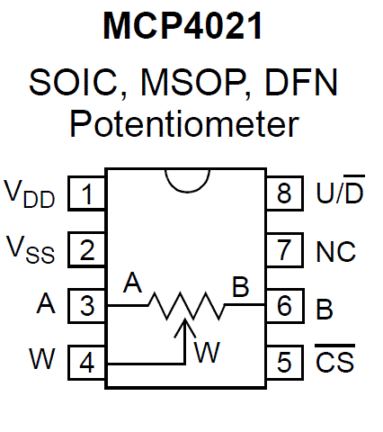
Hi Premelec,MCP41050 is SPI interface and 255 taps - MCP4021 only 64 taps and UP/Down - you need to settle on just what you need...
Thanks for the help! I am assuming the MPC4021 (U/D) would be easier to understand and write the code (for me). I guess I could always try the other chip later since it wouldn't require a change to the original controller once that analog pot is removed.
Does it connect like this from http://www.bristolwatch.com/picaxe/ad5220_button_demo.htm (Also some simple code on that page.) ?
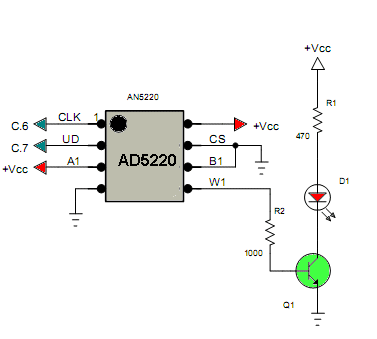
NC the same as CLK for the chip from BristolWatch? (A,B and W coming from the original pot?)
Could I use the AD5220 as well? It is available in a 50k version.
With a chip that has the 255 taps, is there a simple example of the SPI code to address position 125 for the 18M2?
Thanks!
Take care, Joe.
Last edited:
joe paul
Senior Member
Hi Premelec and Everyone,
Instead of talking in hypotheticals, right now let's say I want to use the AD5220 in the 50K version with the following untested code:
This is just something to turn up the speed by about 10 steps, then down, and keep repeating (not tested; don't have the chips yet or the spare controller).
Can something this simple be done with SPI and the chip with 255 taps with the 18M2 chip?
Is SPIOUT available on the 18M2 chip?
Thanks!
Take care, Joe.
Instead of talking in hypotheticals, right now let's say I want to use the AD5220 in the 50K version with the following untested code:
Code:
HIGH C.6

main0:

LET b1=0
LET b2=0


main1:

HIGH C.7
pulsout C.6, 200
pause 100
LET b1=b1+1
IF b1>10 THEN GOTO main2
goto main1


main2:

LOW C.7
pulsout C.6, 200
pause 100
LET b2=b2+1
IF b2>10 THEN GOTO main0
goto main2Can something this simple be done with SPI and the chip with 255 taps with the 18M2 chip?
Is SPIOUT available on the 18M2 chip?
Thanks!
Take care, Joe.
Last edited:
westaust55
Moderator
Have a look at the information and program examples for various Divital Pots that I posted some time ago:
http://www.picaxeforum.co.uk/showthread.php?14087-Digital-Potentiometers-101
Includes for example the MCP410x0 series.
http://www.picaxeforum.co.uk/showthread.php?14087-Digital-Potentiometers-101
Includes for example the MCP410x0 series.
joe paul
Senior Member
Hi Westaust55,
Thanks for the reply and the excellent tutorial! I am trying to understand it. I gather those subroutines execute much faster than the simulation. I would like to be able to address a particular position on the pot. I don't need fine control, perhaps only 10 positions over the 256. Is there an example of a few lines of code to set the pot at one particular position without incrementing or decrementing? Unfortunately, I learn by examples and the building of the bites with the subroutines is beyond me right now. Back when I was in college in 1977, I memorized a routine to alphabetize a list of words (in BASIC Plus), but I didn't understand it. The gray matter hasn't improved since!
Take care, Joe.
I think I understand the example from the bristolwatch site, but would like to directly address a position on the pot.
Take care, Joe.
joe paul
Senior Member
Hi Folks,
I have been going over tutorials but don't understand.
Does anyone have a simple example of a few lines of code for the 18M2 to set the MCP41050 to wiper position 100 (or any single position)?
This would help me tremendously. (I learn by examples.)
Thanks!
Take care, Joe.
I have been going over tutorials but don't understand.
Does anyone have a simple example of a few lines of code for the 18M2 to set the MCP41050 to wiper position 100 (or any single position)?
This would help me tremendously. (I learn by examples.)
Thanks!
Take care, Joe.
Last edited:
You can try the following code tested with an 18m2 and a MCP4231. The code is a stripped down version of westaust55's code. I hope he doesn't mind.Does anyone have a simple example of a few lines of code for the 18M2 to set the MCP41050 to wiper position 100 (or any single position)?
Code:
[color=Green]'stripped down version of following program
; =================================================
;   File....... MCP41010 digital Potentiometer test program
;   Purpose....
;   Author..... Westaust55
;   E-mail.....
;   Started.... 18-12-2009
;   Updated....
; =================================================
;
;

'modified by Rick100 to write a single value to pot and end[/color]

[color=Navy]#picaxe [/color][color=Black]18m2[/color]
[color=Navy]#terminal 4800[/color]

[color=Green]; Define the PICAXE Digital Outputs[/color]
[color=Blue]SYMBOL CS      [/color][color=DarkCyan]= [/color][color=Blue]B.4          [/color][color=Green]; the MCP41050 CS pin connects to PICAXE output[/color]
[color=Blue]SYMBOL SClk    [/color][color=DarkCyan]= [/color][color=Blue]B.5          [/color][color=Green]; the MCP41050 SCK pin connects to PICAXE output[/color]
[color=Blue]SYMBOL SData   [/color][color=DarkCyan]= [/color][color=Blue]B.6          [/color][color=Green]; the MCP41050 SI  pin connects to PICAXE output
;
; - - - - - - - - - - - - - - - - - - - - - - - - - - - - - - - - - - - -[/color]


[color=Blue]SYMBOL [/color][color=Purple]wiper   [/color][color=DarkCyan]= [/color][color=Purple]b1           [/color][color=Green]; step/position of the digital pot wiper[/color]
[color=Blue]SYMBOL [/color][color=Purple]index   [/color][color=DarkCyan]= [/color][color=Purple]b2[/color]
[color=Blue]SYMBOL [/color][color=Purple]mask    [/color][color=DarkCyan]= [/color][color=Purple]b3[/color]
[color=Blue]SYMBOL [/color][color=Purple]datbyte [/color][color=DarkCyan]= [/color][color=Purple]b4           [/color][color=Green]; digital pot data byte (low byte of w2)[/color]
[color=Blue]SYMBOL [/color][color=Purple]control [/color][color=DarkCyan]= [/color][color=Purple]b5           [/color][color=Green]; digital pot command byte (high byte of w2)[/color]
[color=Blue]SYMBOL [/color][color=Purple]varout  [/color][color=DarkCyan]= [/color][color=Purple]w2           [/color][color=Green]; command + data bytes as a word to the digital pot


;
; - - - - - - - - - - - - - - - - - - - - - - - - - - - - - - - - - - - -
; Define constants[/color]

[color=Blue]SYMBOL writedata [/color][color=DarkCyan]= [/color][color=Navy]%00010001  [/color][color=Green];command byte for writing a value to pot 0


      [/color][color=Blue]HIGH CS                 [/color][color=Green];     set the chip select high to disable serial control
      [/color][color=Blue]LOW SClk

      PAUSE [/color][color=Navy]2000

      [/color][color=Purple]wiper [/color][color=DarkCyan]= [/color][color=Navy]100             [/color][color=Green]'pot position
      [/color][color=Blue]sertxd([/color][color=Black]#[/color][color=Purple]wiper[/color][color=Black],[/color][color=Navy]13[/color][color=Black],[/color][color=Navy]10[/color][color=Blue])    [/color][color=Green]'write it to terminal window
      [/color][color=Purple]control [/color][color=DarkCyan]= [/color][color=Blue]writedata     [/color][color=Green];put control byte into high byte of word variable varout
      [/color][color=Purple]datbyte [/color][color=DarkCyan]= [/color][color=Purple]wiper         [/color][color=Green]'put data byte into low byte of word variable varout
      [/color][color=Blue]GOSUB [/color][color=Black]ShiftOutMSBFirst  [/color][color=Green];send it to the chip[/color]

[color=Black]waitHere:
      [/color][color=Blue]goto [/color][color=Black]waitHere[/color]
[color=Green];


; = = = = = = = = = = = = = = = = = = =  = = = = = = = = = = = = = = = = =
; Subroutine to shift the 16 bits out to the digital potentiometer[/color]
[color=Black]ShiftOutMSBFirst:
      [/color][color=Blue]LOW CS                              [/color][color=Green]; set the Chip Select line low to enable the digital pot
      [/color][color=Blue]FOR [/color][color=Purple]index [/color][color=DarkCyan]= [/color][color=Navy]0 [/color][color=Blue]TO [/color][color=Navy]15                 [/color][color=Green]; number of bits to send
            [/color][color=Purple]mask [/color][color=DarkCyan]= [/color][color=Purple]control [/color][color=DarkCyan]AND [/color][color=Navy]$80        [/color][color=Green]; set the mask flag bit based on data bit to be sent
            [/color][color=Blue]LOW SData                     [/color][color=Green]; set the serial data line low
            [/color][color=Blue]IF [/color][color=Purple]mask [/color][color=DarkCyan]= [/color][color=Navy]0 [/color][color=Blue]THEN [/color][color=Black]skiponlow    [/color][color=Green]; if data bit = 0 then leave data line low
            [/color][color=Blue]HIGH SData                    [/color][color=Green]; if data bit = 1 then set serial data line high[/color]
[color=Black]Skiponlow:  [/color][color=Blue]PULSOUT SClk[/color][color=Black],[/color][color=Navy]1                [/color][color=Green]; pulse the serial clock line to tranfer data bit
            [/color][color=Purple]varout [/color][color=DarkCyan]= [/color][color=Purple]varout [/color][color=DarkCyan]* [/color][color=Navy]$02         [/color][color=Green]; move data one bit (left) toward MSB - datbytes is pushed thru control byte[/color]
[color=Blue]NEXT [/color][color=Purple]index                          [/color][color=Green]; loop back for next bit
      [/color][color=Blue]HIGH CS                             [/color][color=Green]; Set the CS line high to transfer data into the digital pot register
[/color][color=Blue]RETURN [/color][color=Green]; return to calling program[/color]Good luck,
Rick
joe paul
Senior Member
Hi Rick,You can try the following code tested with an 18m2 and a MCP4231. The code is a stripped down version of westaust55's code. I hope he doesn't mind.
I don't have a 41050 to test it on. I just looked at the datasheet. Maybe it will work.
Good luck,
Rick
Wow!!! Many thanks for that code and taking the time to work it out! I will be going over it. I think I am starting to understand it. This is a tremendous help because I need examples. I don't have my chips yet, but I am ordering a few different ones.
Again, thanks!
Take care, Joe.
joe paul
Senior Member
Hi Rick,
I have been experimenting with your code (and Westaust55's) to receive serial from the Android app and the HC-06:
It seems to work in the simulator if I haven't screwed things up.
Will know more when I get those chips!
Thanks again!
Take care, Joe.
I have been experimenting with your code (and Westaust55's) to receive serial from the Android app and the HC-06:
Code:
#picaxe 18m2
setfreq m8

; Define the PICAXE Digital Outputs
SYMBOL CS      = B.4          ; the MCP41050 CS pin connects to PICAXE output
SYMBOL SClk    = B.5          ; the MCP41050 SCK pin connects to PICAXE output
SYMBOL SData   = B.6          ; the MCP41050 SI  pin connects to PICAXE output
;
; - - - - - - - - - - - - - - - - - - - - - - - - - - - - - - - - - - - -

SYMBOL position = b0           ; serin from remote app
SYMBOL wiper    = b1           ; step/position of the digital pot wiper
SYMBOL index    = b2
SYMBOL mask     = b3
SYMBOL datbyte  = b4           ; digital pot data byte (low byte of w2)
SYMBOL control  = b5           ; digital pot command byte (high byte of w2)
SYMBOL varout   = w2           ; command + data bytes as a word to the digital pot


;
; - - - - - - - - - - - - - - - - - - - - - - - - - - - - - - - - - - - -
; Define constants

SYMBOL writedata = %00010001  ;command byte for writing a value to pot 0


waitHere:
serin C.0, T9600_8,b0         ; value from serin from remote


      HIGH CS                 ;     set the chip select high to disable serial control
      LOW SClk


      wiper = position             'pot position
      sertxd(#wiper,13,10)    'write it to terminal window
      control = writedata     ;put control byte into high byte of word variable varout
      datbyte = wiper         'put data byte into low byte of word variable varout
     IF b0<>0 THEN GOSUB ShiftOutMSBFirst:
      goto waitHere


;


; = = = = = = = = = = = = = = = = = = =  = = = = = = = = = = = = = = = = =
; Subroutine to shift the 16 bits out to the digital potentiometer
ShiftOutMSBFirst:
      LOW CS                              ; set the Chip Select line low to enable the digital pot
      FOR index = 0 TO 15                 ; number of bits to send
            mask = control AND $80        ; set the mask flag bit based on data bit to be sent
            LOW SData                     ; set the serial data line low
            IF mask = 0 THEN skiponlow    ; if data bit = 0 then leave data line low
            HIGH SData                    ; if data bit = 1 then set serial data line high
Skiponlow:  PULSOUT SClk,1                ; pulse the serial clock line to tranfer data bit
            varout = varout * $02         ; move data one bit (left) toward MSB - datbytes is pushed thru control byte
NEXT index                          ; loop back for next bit
      HIGH CS                             ; Set the CS line high to transfer data into the digital pot register
RETURN ; return to calling programWill know more when I get those chips!
Thanks again!
Take care, Joe.
Last edited:
joe paul
Senior Member
Hi Rick100,
Unbelievable!!!!! Your code (adapted from Westaust55's) works perfectly!!!!! I would be very lost right now if you hadn't taken the time to write an example for me that I could get may head around. I can't thank you enough!!!!!!!!!!!!! WOW!!!!!!!!!!!!
Many thanks!!!!!!!!!!!
Take care, Joe.
[video]https://youtu.be/G8RKFoJEWNY[/video]
Code:
'stripped down version of following program
; =================================================
;   File....... MCP41010 digital Potentiometer test program
;   Purpose....
;   Author..... Westaust55
;   E-mail.....
;   Started.... 18-12-2009
;   Updated....
; =================================================
;
;

'modified by Rick100 to write a single value to pot and end
'modified by Joe Paul Rampolla for Lionel train controller circuit and HC-06 transceiver

#picaxe 18m2
setfreq m8

; Define the PICAXE Digital Outputs
SYMBOL CS      = B.4          ; the MCP41050 CS pin connects to PICAXE output
SYMBOL SClk    = B.5          ; the MCP41050 SCK pin connects to PICAXE output
SYMBOL SData   = B.6          ; the MCP41050 SI  pin connects to PICAXE output
;
; - - - - - - - - - - - - - - - - - - - - - - - - - - - - - - - - - - - -


SYMBOL wiper    = b1           ; step/position of the digital pot wiper
SYMBOL index    = b2
SYMBOL mask     = b3
SYMBOL datbyte  = b4           ; digital pot data byte (low byte of w2)
SYMBOL control  = b5           ; digital pot command byte (high byte of w2)
SYMBOL varout   = w2           ; command + data bytes as a word to the digital pot


;
; - - - - - - - - - - - - - - - - - - - - - - - - - - - - - - - - - - - -
; Define constants

SYMBOL writedata = %00010001  ;command byte for writing a value to pot 0


waitHere:
serin C.0, T9600_8,b0,b6         ; value from remote, 10 preset pot positions

if b6 = 48 then let b1=1   :goto outtopot :end if
if b6 = 49 then let b1=81  :goto outtopot :end if
if b6 = 50 then let b1=94  :goto outtopot :end if
if b6 = 51 then let b1=107 :goto outtopot :end if
if b6 = 52 then let b1=120 :goto outtopot :end if
if b6 = 53 then let b1=133 :goto outtopot :end if
if b6 = 54 then let b1=147 :goto outtopot :end if
if b6 = 55 then let b1=160 :goto outtopot :end if
if b6 = 56 then let b1=173 :goto outtopot :end if
if b6 = 57 then let b1=186 :goto outtopot :end if


outtopot:

      HIGH CS                 ;     set the chip select high to disable serial control
      LOW SClk


      sertxd(#wiper,13,10)    'write it to terminal window
      control = writedata     ;put control byte into high byte of word variable varout
      datbyte = wiper         'put data byte into low byte of word variable varout


; = = = = = = = = = = = = = = = = = = =  = = = = = = = = = = = = = = = = =
; Subroutine to shift the 16 bits out to the digital potentiometer
ShiftOutMSBFirst:
      LOW CS                              ; set the Chip Select line low to enable the digital pot
      FOR index = 0 TO 15                 ; number of bits to send
            mask = control AND $80        ; set the mask flag bit based on data bit to be sent
            LOW SData                     ; set the serial data line low
            IF mask = 0 THEN skiponlow    ; if data bit = 0 then leave data line low
            HIGH SData                    ; if data bit = 1 then set serial data line high
Skiponlow:  PULSOUT SClk,1                ; pulse the serial clock line to tranfer data bit
            varout = varout * $02         ; move data one bit (left) toward MSB - datbytes is pushed thru control byte
NEXT index                          ; loop back for next bit
      HIGH CS                             ; Set the CS line high to transfer data into the digital pot register
      goto waitHere
Last edited:
Your welcome. I enjoyed your video but I'm curious about how your getting reverse with just a pot connection.Many thanks!!!!!!!!!!!]
Good luck,
Rick
joe paul
Senior Member
Hi Rick,Your welcome. I enjoyed your video but I'm curious about how your getting reverse with just a pot connection.
Good luck,
Rick
There is an electronic reversing circuit board in the locomotive (actually in the tender in the video).

When power is cut, it advances the reversing circuit to the next position when power returns. FORWARD-NEUTRAL-REVERSE-NEUTRAL, etc. It is a throw-back to the old mechanical reversing mechanisms. Most of the "e-units" have a neutral position between the forward and reverse. For the old AC wiring, the e-unit changed the AC polarity (hot vs ground) to the motor's armature, and the field windings stayed the same. With the new can motors with permanent magnets, it rectifies then just reverses the DC polarity to the whole motor. Because the old Lionel-type 3 rail trains use a DC off-set on the AC rails to deliver whistle and bell control, the AC is a standard. Funny thing is the old open frame motors do run on DC. Picaxre PWM DC even works on the old motors, but you don't have the beloved whistle and bell control. The Lionel controller in this project has a nice feature that puts that DC off-set and slight voltage boost to the rails for those whistle and bell circuits that are usually in a tender. I will be using that feature with a relay connected to the push button contacts on the controller. I did it before in this analog project about 7 years ago. http://www.josephrampolla.com/commandcontrol.html
Take care, Joe.
Last edited:
joe paul
Senior Member
Hi Folks,
When I introduced the turnouts/switches into the equation, I get an issue where the chip's wiper seems to go to a certain position when there is a spike on the rails. That controller is sensitive to spikes, which are very common with the non-derailing feature of the turnouts. It doesn't reset to the default position as best I can tell, but some other consistent position. I was wondering if there are any tricks to prevent some feedback to the chip's wiper (filters, resistors, chokes, etc.).
Right now I am using a 'timeout' on the SERIN line to repeat the last wiper position as a work around/correction (slows down response time of the remote), but I think this is a hardware issue, most likely the inexpensive controller.
Any suggestions appreciated. I can change the turnouts to isolate the solenoids (causing the spikes on the common rail), but I'd rather not.
Thanks!
Take care, Joe.
When I introduced the turnouts/switches into the equation, I get an issue where the chip's wiper seems to go to a certain position when there is a spike on the rails. That controller is sensitive to spikes, which are very common with the non-derailing feature of the turnouts. It doesn't reset to the default position as best I can tell, but some other consistent position. I was wondering if there are any tricks to prevent some feedback to the chip's wiper (filters, resistors, chokes, etc.).
Right now I am using a 'timeout' on the SERIN line to repeat the last wiper position as a work around/correction (slows down response time of the remote), but I think this is a hardware issue, most likely the inexpensive controller.
Code:
serin [500, outtopot], C.0, T9600_8,b0,b6Thanks!
Take care, Joe.
joe paul
Senior Member
Hi Rick,Hello Joe,
Thanks for the explanation of the reversing mechanism. In your video, I didn't see a decoupling cap across the power supply pins of the digital pot. You could try adding a .1 microFarad capacitor.
Good luck,
Rick
Many thanks for the reply! O.K. The cap across the power pins didn't make a noticeable difference. However it got me thinking and I put a 0.22 mfd cap across the 5+ and wiper on the Lionel controller, and that did the magic. This might also be the solution for the basic issue with the design of that controller which is very sensitive to spikes. So far, so good! You got me thinking about decoupling. I don't fully understand it, but seems to work. I won't know for sure until I get that 'timeout' out of the code.
Things are looking up!
Take care, Joe.
joe paul
Senior Member
Hi Rick and Everyone,
Here is the chip with the way I did the caps (new board). Seems to have solved the issue. Thanks!
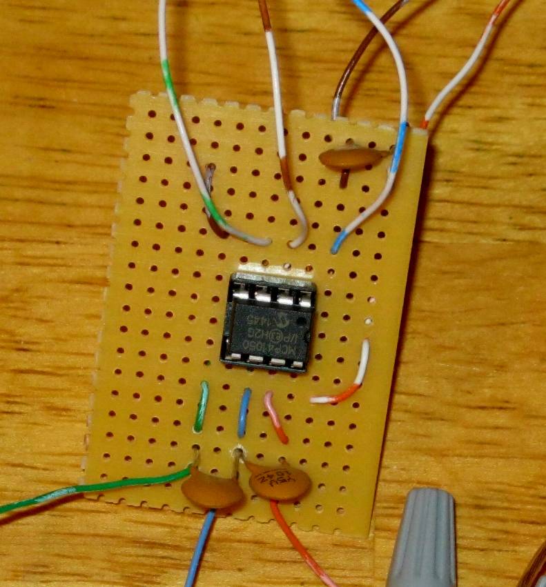
Caps A to wiper and wiper to B, and also on the power pins (solid brown and red stripe).
Wiper is blue, A is red and B is green. B.4 CS is blue stripe, B.5 SCK brown stripe, and B6. SI green stripe.
Take care, Joe.
Here is the chip with the way I did the caps (new board). Seems to have solved the issue. Thanks!
Caps A to wiper and wiper to B, and also on the power pins (solid brown and red stripe).
Wiper is blue, A is red and B is green. B.4 CS is blue stripe, B.5 SCK brown stripe, and B6. SI green stripe.
Take care, Joe.
Last edited: