Picaxe to Picaxe using tones over RF

212

Senior Member
OK...I'm back playing with this RF VCR control once again. I have a camera and RF transmitter way down yonder, and I want to start a VCR recording when the transmitter is sending video. To tell the VCR when to record, I tried using serin/serout, and had good results using wires....thanks for the help. I'm almost sure I can't go straight into my A/V transmitter with that though, because it is very loud when connected to an audio input on my TV set... Soooo, back to tones I guess, I know I can use that, and prefer it really.

hippy asked "Would SOUND/PWM/bit-banging for the transmitter and PULSIN/COUNT for the receiver not work for dealing with tone only ?"

Probably so? I am transmitting sound 2,(100,250) ‘ freq 100, length 250, and using an LM567 on the receiver end, and it works great. I have not learned how to use a Picaxe to listen for the sound yet, and I sure want to. Any further help with that would be greatly appreciated :)
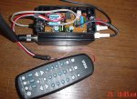
 

moxhamj

New Member
If serin/serout works with wires it should work just as well with radio. The sound a serout makes is just a tone anyway - the frequency is the baud rate and if you are sending a "U" 01010101 it will sound just like a square wave. If the audio is sending cleanly then radio will work fine. And if the audio is not clean, then tones may not be much more reliable. I've played with tones sending ultra slow serial (0.1 baud) and there is a slight improvement in reliability compared with serin/serout but the code ends up 100 lines instead of 1.

Just for starters, do you have a CRO, and can you set up a picaxe at the Tx sending a tone and see what the waveform looks like on the Rx.
 

212

Senior Member
I wish I did have a CRO, but I sure don't. The RF units, I have, accept 0,7Vpp ~ 1,0 Vpp for audio in. I am not able to accurately measure what is coming out of the picaxe using serout, but I think it has to be a lot more than that. I did try using a resistor to cut down the "volume" but it stoped working ...even if I cut it down little bit. This was all hard-wired though, I can't afford to risk damage to my transmitter.

http://cgi.ebay.com/2-Watt-915-MHz-ATV-FM-Video-Audio-Transmitter_W0QQitemZ140212624322QQihZ004QQcategoryZ4675QQcmdZViewItemQQ_trksidZp1742.m153.l1262
 

moxhamj

New Member
Ah, true audio! Nice units by the way. I might bookmark that link.

Most audio works with 1V peak to peak. A picaxe outputs 5V, so a simple answer would be to divide by 5 with some resistors. Something like 39k and 8.2k. Picaxe to the 39k. Low volume out at the join of the two resistors and the other end of the 8.2k to ground. The RF stage may or may not be DC isolated. If not sure, maybe a fat 1uF greencap between the resistor divider and the input to the RF transmitter.

Then you might need to shape the audio out the other end - that might be some op amps. Use another 1uF greencap to isolate the DC, bias the signal after the cap at 2.5V with two 10k resistors, and feed that into the + of an op amp and bias the -ve at 2.5V. If you use a LM324 powered from 5V the output will swing 0V to 4V which a picaxe will accept as a digital signal for serin.

I struggled without a CRO for years. Got one on ebay for $129. Has paid for itself many times!
 

212

Senior Member
I'm afraid if I found one on the side of the road I wouldn't be able to figure out how to use the thing anyway. I have been asked several times now If I had one, so should at least try I guess. Next time you go looking at stuff over there, see if you see one for dummies, I would'nt even know what to look for :(

OK...so I can still use serout, but I'll have to use more circuitry? Well, to be honest, since I already have the tone encoders and decoders, I might as well use those. I'm not complaining about how they work, they do a good job, I was just hoping to get the Picaxe to do it alone.

Oh, I got both the RX and TX, unused, for $66, and a big old Yagi too, for another $5. I felt a little guilty, but that's ebay...
 

moxhamj

New Member
If you already have some circuitry built then use that. Do you have a schematic for the tone encoders? I guess first step would be to connect them to each other with a wire and leave out the RF and see if the signal goes through. Then add the RF though you might still need some signal conditioning.
 

212

Senior Member
Yes, I have already used the encoder/decoder, click on projects, then PL Tone Encoder board. http://www.rason.org/index.html The decoder uses the same basic circuit, but does not need the transistor audio amp. I posted my own design on another site, but it is down at this moment???

I have had this project... hobby...obsession...for a couple of years. The main reason I started playing with the Picaxe, is I wanted an easier way to control my universal remote. Before Picaxe, it was a lot harder because you have to press the record twice to record with this remote. This receiver (in the picture) is a 2.4ghz one, and it has two audio channels, the one I want to try next has only one. I have been sending a continuous audio tone, but now I need to share the channel with the cameras audio. I intend to only send a start and stop tone when it needs to do something useful. I have a Picaxe sending tone now, in place of the encoder on the transmit end. I used a filter found in the editors tone wizard help file. I added a volume control and it works well. I wanted to try using the serin/serout to simplify the receiver set-up is all. I think the Picaxe can "decode" tones, but have not found how yet.
 

Attachments

moxhamj

New Member
Revised post - I'm working through this - The 567 can be configured as an encoder or a decoder. I think your schematic is only half the circuit. The generator part can be done within a picaxe which could save some components. I'm looking round for a decoder schematic...
 
Last edited:

212

Senior Member
Ok, the site was back up. Here is what I used before Picaxe came into my life. This will control a VCR, but you have to hardwire hack into it. On the lower right there is info on a kit you can buy for the encoder and decoder part of it. They have a PDF there with the schematic and parts list too. Duncan is a member here too, but he does not post much, thank you Duncan for the help with the project, Duncan built the first one, and it still works too :)
 

Attachments

Last edited:

212

Senior Member
I'm not very good with words and probably did not get across what I'm after. I already have a working unit, and I have a picaxe on the transmitter end sending sound 2,(100,250) ‘ freq 100, length 250 through the audio channel. On the receive end I have an LM567 tone decoder and a Picaxe. When the LM567 hears the right tone from the transmitter, it triggers the Picaxe on the receiver end to run this codeVVVVVVVV

I am asking if I can decode sound 2,(100,250) ‘ freq 100, length 250 with my Picaxe, so I can eliminate the LM567 on the receive end and replace main???


symbol counter = b1

low 0 'led output off
low 1 'record button relay off
low 2 'stop button relay off
low 4 'power button relay

main:

if pin3 = 0 then recheck 'if input 3 is low, check again
if pin3 = 1 then goto main 'if input is high, do a loop

recheck: 'checking to be sure a real trigger happened

high 0 'turn on yellow LED
pause 300 'pause 3/10 second
low 0 'turn off yellow LED
if pin3 = 0 then record 'if pin 3 is still then record video
if pin3 = 1 then goto main 'if it was a false, then return and wait for event

record:

high 0 'turn on yellow LED
high 4 'turn on power button relay...if used
pause 300 'wait 3/10 second
low 4 'turn off power button relay
pause 300 'wait 3/10 second
high 1 'turn on record relay
pause 300 'wait 3/10 second
low 1 'turn off record relay
pause 300 'wait 3/10 second
high 1 'turn on record relay again....for universal remote to work with this
pause 300 'wait 3/10 second
low 1 'turn off record relay
pause 1000 'wait 1 second
goto recording

recording:

if pin3 = 1 then make_sure 'if pin 3 goes high, check it again before doing anything
if pin3 = 0 then goto recording 'if pin 3 is still low, keep recording

make_sure:

pause 1000 'wait 1 second before checking pin3
if pin3 = 1 then quit 'if pin3 is in fact still high, then it is time to stop recording
if pin3 = 0 then goto recording 'if pin3 is still low, then keep recording

quit:

high 2 'turn on stop relay
pause 1000 'wait 1 second
low 2 'turn off stop relay
low 0 'turn off yellow LED
pause 1000 'wait 1 second
high 4 'turn on power relay
pause 1000 'wait 1 second
low 4 'turn off power relay


for counter = 1 to 5 'blink yellow LED to show a time delay for VCR to stop and turn off

high 0 'turn on yellow LED
pause 500 'wait 5/10 second
low 0 'turn off yellow LED
pause 500 'wait 5/10 second

next counter 'this will blink yellow LED 5 times
pause 100 'just wait 1/10 second

goto main 'now we wait for another event
 
Last edited:

moxhamj

New Member
I think the 567 is going to end up the simplest decoder. A picaxe can decode clean signals but not noisy ones. Say you had a nice clean sine wave and then someone talks on that frequency as well. To reject that speech needs advanced digital signal processing - send in the raw waveform into a DSP with a very fast A-D (much faster than picaxe) then run digital filters and echo rejection and FFTs and other clever things. It can certainly be done and these chips existed 15 years ago but it is the expensive solution. A pic running raw machine code might struggle though the new chips with Sin and Cosine functions might be able to do something. Seems a hard way to do it though.

But if the 567 can decode a tone and give a high or a low digital signal then a picaxe can do all sorts of clever things with that. You can send morse code. You can send a binary version of morse code which replicates the RS232 protocol but with each pulse 1 second long instead of 1/2400th second. I can post some code for slow binary if you like.

Or if you are just turning things on and off, maybe the setup is fine like it is. The 567 is doing things that can't be replicated in a picaxe and it is quite a cheap chip.
 

212

Senior Member
Thank you for the reply sir, I've been searching and reading all I can to get the answer. Yes the 567 does work well, and it is cheap and easy enough to use too. Now that's answered I can stop wondering and get on with the project :)

One of these days I'm going to want to try sending commands to a PTZ camera too, but I need to learn more basic stuff first huh...can you tell...I'm having a blast :)
 

manuka

Senior Member
Dr_A is not teasing with his slow binary. Simply greatly underclock both PICAXEs to perhaps even as slow as ~31kHz (which is 4MHz/.031MHz or ~1% of normal), & their serial will sound akin to slow Morse code. Regular slow 300bps will then be more like 3bps, with a single byte taking ~2 secs. Yeah- it's like waiting for paint to dry- slow but sure.

Here's a posting on this (made over 3 years ago) via fellow Kiwi "BrightSpark" Andrew, who'd been POKEing a 08M to gain UNDER clocking insights. This technique could be handy for noisy wireless serial links + the slower clock should also use less battery energy.

Code:
'Andrew Hornblow => picaxe@paradise.net.nz (Web => www.picaxe08.orcon.nz)
'Internal clock frequency can be tinkered easily on an 08M as follows
'(Notes from Microchip documentation for 08M hardware)
'REGISTER 3-2: OSCCON - OSCILLATOR CONTROL REGISTER (ADDRESS: 8Fh)
'
'%00000000 = 31 kHz ~19bps  (UNDERCLOCKED)
'%00010000 = 125 kHz 75bps  (UNDERCLOCKED)
'%00100000 = 250 kHz 150bps (UNDERCLOCKED)
'%00110000 = 500 kHz 300bps (UNDERCLOCKED)
'%01000000 = 1 MHz 600bps   (UNDERCLOCKED)
'%01010000 = 2 MHz 1200bps  (UNDERCLOCKED)
'%01100000 = 4 MHz 2400bps  (NORMAL)
'%01110000 = 8 MHz 4800bps  (OVERCLOCKED)

loop:
poke $8F,%01100000                   'Set clock to 4 MHz
pause 5                              'Pause  to allow clock stabilising
pulsout 2,10                         'Sample pulse out Pin 2 to flash LED
sound 4,(100,5)                      'Sample sound out Pin 4 to beep  piezo
serout 1,n2400,("Hello World",13,10) 'Send serial text message Pin 1
poke $8F,%00000000                   'Change clock to another value (see above)
pause 5                              'Pause to allow clock stabilising
pulsout 2,10                         'Sample pulse out Pin 2 to view difference on LED
sound 4,(100,5)                      'Sample sound out Pin 4 to hear piezo clicks
serout 1,n2400,("Hello World",13,10) 'Send text message Pin 1 at lower baud rate!
goto loop
It's fun to see this with a serial flashed LED, & it sounds almost akin in fact to clicking Morse. However the AGC (gain) on some receivers may snooze between such tardy bits,corrupting data.
 
Last edited:

moxhamj

New Member
And thankyou to you as well, because that 567 circuit is quite nifty. I have a few in a drawer - I might see if I can get this working myself. Picaxe transmitter and 567 receiver I think is a good combination. Sing out if you need that slow binary code.
 

manuka

Senior Member
I've done a lot with 567s in a pre micro life,& they certainly will work, BUT good old DTMF (Dual Tone Multi Frequency) is far superior- even a sniff of it in noisy RF circuits will usually be reliably detected. Sigh... this brings us back to the old PICAXE + DTMF = answer to a prayer saga of course.

Keep in mind 567s use boring old hard wired caps & resistors to set tone & bandpass freqs. It may be possible to PICAXE tweak these values of course. Mmm-PWM LED shining on a shrouded LDR?

Dr_A extra: Have just posted off that HM-TR 433 MHz pair OK. Cancel appointments ~Friday!?
 
Last edited:

212

Senior Member
manuka, thanks for posting that code! I had seen it before somewhere and had copied just one of the lines to play with. I wanted to try more speeds, but could not find it again! I have also seen where you can use two Picaxes and get the DTMF, but that is way beyond me for now. "use boring old hard wired caps & resistors" now that's more my speed :) I do want to try the chips made just for that DTMF someday, but I'm bad about having too many things going at once and nothing ever gets finished.


"Sing out if you need that slow binary code." Dr_Acula, you have been a great help already, but I better try to get one thing going now before I start on something else. I've got parts and pieces of projects scattered all over the place :)

I did not find this site on my own, but I'm sure glad I got here. You guys are sooo helpful and friendly to people...Thank you!
 

Mycroft2152

Senior Member
All kidding aside. It was an amazing achievement.

I was fortunate to be involved in the MARS Pathfinder mission. Remember the little Sojourner Rover.

I was in charge of the qualtiy control lab at a textile processing plant. We were hired by Pioneer Aerospace and JPL to process the fabric used for the main parachute. I had to test and certify the fabric meet the specifications.

Believe me, I fully understand the comment by the Phoenix's ground crew of "Seven minutes of teror" while the parachute deployed.

I managed to keep some fabric remnants from that project.

For the PICAXErs here on the forum, I'll make the following offer:

Send me a private message and I'll snail mail you a small swatch of the fabric used for the Pathfinder Parachute. For those of you outside the US, it would help if you picked up the postage.

Myc
 

Mycroft2152

Senior Member
Dr A.

The PICAXE is on its way...

http://www.planetary.org/blog/article/00001464/

This is an amazing photo of the of the Pheonix Lander parachuting to Mars, taken from the MARS Reconaisance Orbiter.

It's like taking a photo of a speeding bullet from another speeding bullet.

Myc

Mars will have to wait for its PICAXE. I went through the (model) rocketry stage years ago. Though the record will soon be set by the PONGSAT (100K feet) when it is launched.
 

boriz

Senior Member
On the subject of audio over RF.

I’m sure that some of the people here have heard the sound of a program loading from a cassette tape into a ZX81/SPECTRUM/BBC Micro etc.

What format is that? Could it be adapted?
 

moxhamj

New Member
Could this be decoded with two 567s?

The advantage of this over sending raw binary data is the possibility of a long string of 0's unbalancing the radio receiver. With picaxe the data packets are short due to the serin being limited to reading in 14 registers, and with some "U"s at the beginning the average voltage works ok even with a string of 0s or 255s.

Frequency shift keying gets around this problem. There would be no point in using sine waves as most radio data modules send only 1 or 0 so you could go to all the effort of making a sine wave but the radio module will turn it into a square.

One could use a variant on the Kansas standard. Use the same frequencies but use a much slower baud rate. Use two tone decoders. Start with a very slow baud rate, maybe one tone change per second (= 1/10th baud). Feed the input into the registers (as serin is not being used, can send long packets). Then gradually ramp up the baud rate till it fails, then maybe run at half that rate.
 

premelec

Senior Member
Manuka, thaks for that ref to Byte / Wiki on KS cassette standard... I have an HX-20 that uses micro cassettes and VIC20 Commodore Datasettes - Commodore used the JIC feature of recording the program twice [Just In Case!]. I'd forgotten about the Vinyl try and remember 'softstrip' paper coding that didn't last too long - we've come a long way and the basic methods still work...

Drac.. with very slow rates you could even consder PULSIN OOK tone with the tone length indicating 0,1 - with a tone filter giving you better signal to noise ratio. Even a sub-audible tone could work at very slow rates... AFSK probably still works best and demodulation with the 567 is pretty straightforward.
 

MFB

Senior Member
The February 2007 issue of Elektor magazine had a PICAXE based article about sending data over the audio channel of a video link at 1200bps. Basically the same technique as used for data storage on those old audio cassette recorders.

The circuitry employed FX614 modem chips (from CML) at either end of the 2.4Ghz video/telemetry link. The article can be downloaded from the Elektor site and they even sell a pcb to go with the article.
 

moxhamj

New Member
Goodness me, a modem on a chip with a current consumption of just 1mA. This uses FSK, ie a 0 or 1 input turns into a tone and then comes out the other end as a 0 or 1. Presumably a long 0 comes out the other end the same way. I wonder if this could be a path to that longstanding problem of programming a picaxe over a wireless link? Is the baud rate fast enough, for starters? Good find, MFB. I'm off to the elektor site now. [addit - still searching. Is it the rocket telemetry article?]
 
Last edited:

MFB

Senior Member
Dr_Acula, yes it is the rocket article.

I have used these chips on a number of telemetry projects and in the receive mode they have near magical powers of extracting data from noisy signals (good for getting the maximum range from a low power transmitter). This is because, in addition to the FSK decoder, these chips have onboard amplification and filtering circuitry.

This approach really is a wire replacement, as there is no need for special serial coms code. Just the standard 1200 baud serial I/O port format.
 

Zizka

New Member
If FX614 chips can't be found then a basic manchester coder plus framer/packetiser can be got from here: http://www.radiometrix.co.uk/dsheets/nbek_ic.pdf

Although to be fair, this isn't a proper "analogue tone" design (it requires logic level baseband signals) so might not have quite the signal to noise performance of the 614.

If anyone fancies doing a proper performance comparison with an FX614 based link, I'll provide them a pair of the NBEK chips FOC
 
Top