Picaxe resetting intermittently

jst3712

Member
I see R20 is 56ohms. Given a Vbe of about .7V that would mean a current of around 4.3/56=~77mA being drawn off pin 11 of the PICAXE when you turn on RL4. I am not sure that is causing your problem, but it is not advisable at any time.

Good point - miscalculation. Not good for the Picaxe is it.
 

jst3712

Member
Seeing your partial schematic, and reading what you are trying to do, it seems that it may well be a code issue (not seen) - as the Picaxe is switching its own power supply about this may well be the problem - big caps are NOT enough. :confused:
I will work with the hardware first, based on the recommendations - if all fails, will look at the code :)
 

jst3712

Member
First thing is to absolutely prove the PICAXE is resetting and that you are not seeing something else that just happens to look like a reset. Then it's necessary to find exactly when it does reset, determine what the exact sequence of events will be leading up to that.
I know when it's really resetting because I have a program initialization section in my code (only runs once at startup) where the buzzer beeps quickly a few times, and the Mains Failure / Low Batt LEDs flash rapidly.

I am running a few tests to try and reproduce the problem, and at the moment, it seems to reset just after power switches from mains to battery - with a LOAD connected. I need to run a few more tests - "sequence of events" to see much further I can drill down. Will try different loads too.
 

jst3712

Member
Also, the 5v circuit is supplied through R4 and D3 and D4. If the 5v circuit draws about 100mA for example, from a 12v5 supply, as little as 4v could be driving your 5v regulator!

Also, throwing big capacitors into the mix isn't always a good idea. For example, they take a moment to charge, during which they draw a huge current. Easily enough to bring down your supply voltage long enough to cause problems.
Are you referring to capacitor C1 in particular? I think I get what you mean though about the current draw. I thought more capacitance would mean a smoother power transition between battery and ac adapter. I actually was thinking about adding more.

So what do you suggest I do regarding the large caps? Eliminating them will just create a longer disruption to the 12V output during power change-over (currently it's something like 250ms). Having said that, is there a way I can totally get rid of this 250ms or so delay? The delay is caused by internal caps in the 15V adapter (shuts down slowly after you switch off the power point). I don't get the delay if I switch off SW1, but that is not mimicking a real life "power blackout". I have already made it so the Input relay (RL1) turns off a little quicker by reducing the voltage to around 9 volts (zener; voltage high enough to turn coil on and off), but I won't be able to modify the 15V adapter .... someone suggested removing the internal caps at the output for another project I was working on a while back). This adapter is pretty compact. Thanks.
 
Last edited:

rossko57

Senior Member
Having said that, is there a way I can totally get rid of this 250ms or so delay?
Re-read the part about diodes. The suggestion is for the battery to be permanently connected to "power rail" via a diode. No matter what happens to the primary supply, the battery is always connected, so ther can be no delay in changeover. The diode prevents the primary supply trying to overcharge the battery. A second diode in the primary supply line prevents battery power feeding back into it.
 

jst3712

Member
Re-read the part about diodes. The suggestion is for the battery to be permanently connected to "power rail" via a diode. No matter what happens to the primary supply, the battery is always connected, so there can be no delay in changeover. The diode prevents the primary supply trying to overcharge the battery. A second diode in the primary supply line prevents battery power feeding back into it.
Thanks rossko57. Understand the concept about the diodes. However, I don't think the type of charger that I have will allow me to do that (unless I am misunderstanding).

If the battery is to be connected to the main power rail permanently through the diode/s as suggested, this could cause issues for the Charger (the manual says that if currently in 'Float' mode -steady 13.5V-, and it detects more than 300mA of current being drawn from the battery, it will automatically switch back to Bulk/Absorption mode -14.3V-).... and this voltage will be fed to the main power line as well, much higher than 12.6 or so (what I wanted).
Having a digital voltmeter connected to the battery, I can see that the voltage is rising and falling when the charger is in Bulk/Absorption mode, but then sits at a steady 13.4V when it goes back to Float mode (assuming current drawn is less than 300mA).
 

hippy

Ex-Staff (retired)
That diode-mixing will look something like this ...

Code:
            .-----.     :           P
Mains >--.--| PSU |-----:-----------^-|>|---.-------------> 12V
         |  |     |--.  :                   |
         |  `-----'  |  :                   |
         |  .-----.  |  :           B       |   .-----.
         `--| BAT |--|--:---|>|---.-^-|>|---^---| REG |---> 5V
            | CHG |--{  :       __|__           `--.--'
            `-----'  |  :        ___   BATTERY     |
                     |  :         |                |
                     `--:---------^----------------^------> 0V
                        :
As long as mains is present, the voltage at P is greater than at B, the entire system will be powered from the mains supply. As soon as mains fails and P drops below B, the system will be powered from the battery.

You can ensure P is greater than B through selection of the PSU or by adding extra diodes in the battery supply before B.

There are no relay contacts because where power (current) is taken from is a matter of voltage potential; when P is a higher voltage than B current will never come from B, and current won't get from P to B because it has a 'reversed diode' blocking that.
 

hippy

Ex-Staff (retired)
If the battery is to be connected to the main power rail permanently through the diode/s as suggested, this could cause issues for the Charger (the manual says that if currently in 'Float' mode -steady 13.5V-, and it detects more than 300mA of current being drawn from the battery, it will automatically switch back to Bulk/Absorption mode -14.3V-).... and this voltage will be fed to the main power line as well, much higher than 12.6 or so (what I wanted).
That does throw a small spanner into the works. It should however be possible to diode mix the supply for the PICAXE so it gets brownout free operation without exceeding the 300mA float charge limit, even though the lighting output and charger has to be switched.
 

boriz

Senior Member
I am not quite understanding how you came up with '4 volts' at the regulator's input via R4/D3/D4.
If the 5v circuit were to draw 100mA, then that's almost 7v across R4. (V=IR)

And the diodes can drop up to 1.5v

That's about 8.5v lost between your 12.5v supply and the input to your regulator.

12.5 - 8.5 = 4

I estimate any total 5v circuit load greater than about 62mA will force the regulator to operate outside it's specs.

These figures are rough, but close enough that you should be worried. With electronics you should always overestimate your loads, frequencies and gains. Components are rarely 'ideal', and often enough a large overhead is all that's stopping the circuit from failing. (or your Picaxe from resetting)
 

jst3712

Member
That diode-mixing will look something like this ...

Code:
            .-----.     :           P
Mains >--.--| PSU |-----:-----------^-|>|---.-------------> 12V
         |  |     |--.  :                   |
         |  `-----'  |  :                   |
         |  .-----.  |  :           B       |   .-----.
         `--| BAT |--|--:---|>|---.-^-|>|---^---| REG |---> 5V
            | CHG |--{  :       __|__           `--.--'
            `-----'  |  :        ___   BATTERY     |
                     |  :         |                |
                     `--:---------^----------------^------> 0V
                        :
As long as mains is present, the voltage at P is greater than at B, the entire system will be powered from the mains supply. As soon as mains fails and P drops below B, the system will be powered from the battery.

You can ensure P is greater than B through selection of the PSU or by adding extra diodes in the battery supply before B.

There are no relay contacts because where power (current) is taken from is a matter of voltage potential; when P is a higher voltage than B current will never come from B, and current won't get from P to B because it has a 'reversed diode' blocking that.
Hi hippy. I like it.
BUT, the 2 diodes on the Charger/Battery line are concerning me. The one between the charger and battery in particularly..... there will obviously be a voltage drop across that diode, so I am guessing the battery will never see the full charge voltage from the charger, AND the smart charger most likely would get confused and probably get stuck in Bulk/Absorption mode, forever :( If that was to occur, I probably would use a relay contact instead of that particular diode.

As with the second diode between the battery and regulator, again, a voltage drop. Say if the battery terminal voltage is 12.4V (during a power failure), the 12V 'output' would really be something like 11.8V (assuming voltage drop of 0.6V). I'd rather have 12.4V at the output!!! My calculations may not be accurate, but do you get what I'm trying to say? :) Otherwise I think your idea (or whoever mentioned it earlier) would definitely eliminate the delay issue I recently mentioned.
 

srnet

Senior Member
Otherwise I think your idea (or whoever mentioned it earlier) would definitely eliminate the delay issue I recently mentioned.
It was me.

First of all try it as above, it might work.

Second you can probably raise the output of the charger by the same as the diode voltage drop by putting a diode in the ground connection of the charger. At least that normally works with regulators.
 

jst3712

Member
It was me.

First of all try it as above, it might work.

Second you can probably raise the output of the charger by the same as the diode voltage drop by putting a diode in the ground connection of the charger. At least that normally works with regulators.
Happy to try it and see what happens.

As with the diode in the charger... hmm... SMD... lots of IC's... I could ruin it :confused:
Do you think I would need that diode (the ones between the charger and battery)? I am hoping the charger has its output protected already... but that's wishful thinking.
 
Last edited:

hippy

Ex-Staff (retired)
Hi hippy. I like it.
BUT, the 2 diodes on the Charger/Battery line are concerning me.
See post #48 - It should be possible to use a diode-mixed supply for the PICAXE to allow brownout-free operation and use a relay switched supply for the lighting load.
 

jst3712

Member
Hi guys. As there is a lot of information for me to process here (as you can tell by the the number of replies!), I'm now going to take this away and have a play.
First I'll try the easier stuff.... the resistor values, then I'll try running the Picaxe separately off batteries.

This may take me a few days, but I'll let you know how I went and then maybe we can revisit some of the other things mentioned in more detail.

.... I thought this was going to be relatively simple... obviously not :( ....
 

jst3712

Member
Hi guys. Just an update.....

I've discovered that the 'Charger Controller' relays were NOT causing the resets (i.e. the R20 resistor that apparently was too low in resistance), because today I tried disconnecting the RL3/RL4 relays completely, and it was still resetting intermittently just after power was disconnected ('AC mains failure'). Even though it doesn't seem to be the issue, I will replace the R20 (and possibly even the Q3 transistor) anyway. Grrrr, I was hoping it was the R20!!! :mad:

Over the next week or so, I will try the following as recommended (if I understood correctly):
Run Picaxe off 3xAAA batteries and fully test; Remove the big cap C4 from the regulator and change the C5 22uF to a 'Low ESR' type; Reduce R4 to a lower value (I might try 33R?); Connect a 100uF 'Low ESR' cap between relay's +ve and ground (all relays); Try a new chip?; If all fails, I will have to look at completely re-designing my circuit and use Solid State Relays or look for ways to avoid relays completely (which might solve my issue with the brief brownout at the 12V output during power change-over).

If anyone has any comments with regards to anything mentioned here, or if they have come up with any new ideas, please feel free to let me know :) - I will keep you posted. Thanks!
 

Jeremy Harris

Senior Member
When you say you disconnected the relay and the problem persisted, do you mean just the relay, or did you disconnect the resistor from the Picaxe pin?

If you just disconnected the relay, then the same high current would still be flowing from the Picaxe pin via the base emitter diode of the transistor.
 

jst3712

Member
When you say you disconnected the relay and the problem persisted, do you mean just the relay, or did you disconnect the resistor from the Picaxe pin?

If you just disconnected the relay, then the same high current would still be flowing from the Picaxe pin via the base emitter diode of the transistor.
Thanks JH.
Sorry, I forgot to mention that prior to disconnecting the relays, the R20 was replaced with 1K and Q3 replaced with BC548 (to match the LBC (Low Battery Cut-off) relay circuit ... even though I have 2 coils connected... just until I source a proper transistor to drive the 2 coils sufficiently).
 

hippy

Ex-Staff (retired)
If anyone has any comments with regards to anything mentioned here, or if they have come up with any new ideas, please feel free to let me know :)
If you are going to get out of the guessing game of what may be going wrong you are going to have to start looking at what is actually happening and that's likely going to need a scope.

What does the PICAXE supply do when it resets ?
 

srnet

Senior Member
What does the PICAXE supply do when it resets ?
Exactly.

A scope would save a lot of guesswork and forum time.

But as we are guessing my guess is that the supply volts to the PICAXE is dropping enough during the supply changeover to cause the problem.
 

jst3712

Member
Exactly.

A scope would save a lot of guesswork and forum time.

But as we are guessing my guess is that the supply volts to the PICAXE is dropping enough during the supply changeover to cause the problem.
Hi srnet and hippy...
I agree that a scope would help and save time, but I don't have one; they're expensive; I have no idea how to use one - I'm just a hobbyist! haha!
I am still in the process of elimination - I just need some more time. So far with the tests I've performed since my last post, I agree it's most likely to be a problem with the power line feeding into the Picaxe, but not confirmed as yet.
Can I please confirm with you that a 0.1uF "greencap" is sufficient enough to connect across the Picaxe power pins, or is this totally wrong? I'd kick myself if it was this cap all along :S
 

bfgstew

Senior Member
I agree that a scope would help and save time, but I don't have one; they're expensive; I have no idea how to use one - I'm just a hobbyist! haha!
Designed and made for the hobbyist, I have one and they are worth every penny.........................DpscopeSE
 

srnet

Senior Member
A basic scope is not expensive, see the example from bfgstew.

And unfortunately if you don't have one, or cant even borrow one, you can spend a very great deal of time, and forum members time, in trying to identify what exactly the problem is, whereas a scope might find the problem in a couple of minutes. Even if after a time and some changes the problem seems to go away, you might never know the exact cause and the problem might remain, ready to bite back when you least expect it.

So whilst you may not have one, sometimes there is just no practical alternative to having access to one.
 

SteveT

Senior Member
Can I please confirm with you that a 0.1uF "greencap" is sufficient enough to connect across the Picaxe power pins, or is this totally wrong? I'd kick myself if it was this cap all along :S
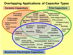
As far as I can tell, a 'greencap' is a type designation for a range of plastic film capacitors. Ceramic capacitors are normally used for decoupling but AFAIK it's down to more of a cost thing. Ceramic are far cheaper than polyester (normally). So yes you can use your 'greencap' 0.1uF. Have a look at 800px-Capacitors-Overlapping-Applications.png

Edit: Graphic taken from the Jaycar site.
 

jst3712

Member
As far as I can tell, a 'greencap' is a type designation for a range of plastic film capacitors. Ceramic capacitors are normally used for decoupling but AFAIK it's down to more of a cost thing. Ceramic are far cheaper than polyester (normally). So yes you can use your 'greencap' 0.1uF. Have a look at View attachment 14422

Edit: Graphic taken from the Jaycar site.
That's good to know. Thanks SteveT.
 
Top