PICAXE in Space

Jeremy Harris

Senior Member
I respectively suggest some rechecking (& a posted picture?) may be in order. In 2012 I'd a student who even confused mm & inches (arising from his dual standard tape measure) when constructing a 433 MHz Yagi. Upon presentation we could see at a glance that it's dimensions were over twice (2.54mm = 1 in) the intended !
When we first introduced CAD/CAM in a place I worked (early eighties, I think) it was US software and defaulted to inches. The CAM plant was about 100 miles away from the CAD drawing office and a punched tape for the first part ( a special nut around 30mm in diameter machined from stainless) was duly despatched. When the lorry turned up with the ~1 tonne, beautifully machined, 30inch diameter nut we knew we had a problem...................

BTW, 1 inch is 25.4mm, so more than 25 times the size if that mistake is made. Must have been a pretty big Yagi...................:D
 

manuka

Senior Member
The tape measure was indeed cm/inches - I'd meant cm but by habit mentally converted to the more UHF antenna friendly mm.

Confusion happens - a traffic engineering mate here in NZ had his plans for feed roading 3m (metres) wide being initially considered by a US contractor as meaning 3 miles.
 

srnet

Senior Member
I would also respectfully point out that I have already checked this. The test has been done on two occasions with a dipole and at least 2 occasions with a 1/4 wave vertical with 2 different field strength meters. Roughly similar results.

Whats clearly happening is that the output stage matching of at least some modules is not 50R at 437Mhz.

I am not saying that all of the Hope modules are affected in the same way, but it appears that some are. So the advice is, If you want maximum range, then you need to forget the calculator and actually check the antenna tuning.

As for confusing mm or cm and inches, no comment.
 

john2051

New Member
Hi srnet:

what are you using as a dipole, open ended or closed loop?
and how are you matching these to 50R?
regards john
 

srnet

Senior Member
Its open ended, and there is no matching between the supposed 50R output Z of the transmitter and the theoretical 73R of the dipole center.
 

manuka

Senior Member
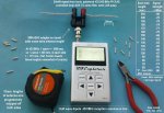
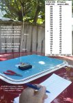
By chance I'm presently evaluating a nifty RF Explorer UHF spectrum analyzer, so used it for an (admittedly quick) 433 MHz reception test. Although the setup tends "barnyard science",results indeed look to confirm classic Yagi ½ wave dipole theory.

Extra: Added companion transmitter end vertical radiator trimming for "srnet". When monitored on the RF Explorer (via it's supplied Nagoya NA-773 vertical antenna) the progressively shortened vertical whip indeed showed best transmitter radiation performance when ~¼ wavelength long. Both PICAXE & transmitter (a cheap & cheerful Dorji ASK 25mW module that's shown itself a great performer) were powered by 3 x AA cells = ~4.5V.

Note-TX & RX were not in exactly the same positions as initially, but moved somewhat for reading & "snipping" convenience. The car roof top made a traditional metallic ground plane, but was NOT electrically connected to the setup. Such findings are consistent with long established terrestrial practise, but in space of course ground planes may well be elusive. For a pico sat. make that VERY elusive! This however doesn't prevent aircraft using ¼ wave whips for VHF communications, as the aircraft structure itself acts as the ground. Stan. (ZL2APS)
 

Attachments

Last edited:

srnet

Senior Member
The RF Explorers are rather good, for the price, and very handy for field tests. One of two methods I have been using to check field strength for my own "barnyard science".

I have no doubt that classical antenna theory is indeed correct, you get maximum received signal strength when the dipole impedance is a close match to the input impedance of the RF Explorer.

Now reverse the test and trim the dipole or 1/4 vertical on the transmitter (keeping the RF explorer in the same position) do you get the same results ?
 

Dippy

Moderator
Is this in space yet? You mentioned a January launch some time ago.
I see a lot of module testing and discussion; does this mean your design is still in doubt? I'm looking forward to seeing results. Hurry up, I'm getting impatient -even North Korea have managed to send up something ;).


And after mentioning the word "design", Pauldesign's mystery item "..something more useful than yours" & "... is classified for now until after October..." has gone very quiet. It's after October so perhaps he can describe it now? I'm intrigued.
 

srnet

Senior Member
See post #107.

And no the design is not in doubt, the current one will work if it survives launch.

From #109;

The picture shows the PCB, the battery is shown for comparison, we are planning to use a slightly smaller one, KLIC 7002 . On top of the PCB there is a maximum power point tracker for the solar panels. There are two of these in the states already, one for a battery powered power board, the other an alternative one using Supercaps. I dont have a decent picture of the assembled bird, there have been some issues with the PCBs for the solar panel mounting (in the US).

If time has allows, the PCB might be changed to one with both the RFM22B (100mW) and RFM23BP (1W).
The dual RFM22B \ RFM23BP PCB board is working, I needed to build one to test it properly, but its yet to be decided if I take it forward
 
Last edited:

manuka

Senior Member
Now reverse the test and trim the dipole or 1/4 vertical on the transmitter (keeping the RF explorer in the same position) do you get the same results ?
Your every wish is my command - see tweaked posting 126 above.
 

srnet

Senior Member
Interesting.

Which Dorji transmitter ?

And for the RF Explorer, the difference between the calculated length (172mm) and the the best length (130mm) was 8dB, so by tuning the antenna you would have got close to 3 times the distance for the same TX power.
 
Last edited:

manuka

Senior Member
Sure - every 6dB improvement doubles range of course. However that RX trial "best length" of 130mm was greatly biased by the bulky SMA-BNC adapter, which had internal conductors that acted as a pick up antenna too! You could see this from the results,as significant signal was still picked up with no external dipole wire at all ! Although convenient,for keener insights it should be replaced by a specialised connector.

The 2nd TX trial (which did NOT need to use this adapter) is consistent with 433 MHz ¼ wavelength vertical antenna optimising at resonant length ~170mm.

The Dorji TX used was their popular 25mW ASK module => www.picaxe.orconhosting.net.nz/dorjiask.htm . These cheap & cheerful modules (~US$4 each) have only been available for ~a year but have established themselves as THE best 433 MHz cheapies around. For quick tests like this they're an automatic choice!
 

srnet

Senior Member
You would expect the the RF Explorer not be an exact match, its a wideband device (a very wideband device depending in the model) and getting a wideband match to 50R is not so easy.

The Dorji module is a single frequency device, so it should be easy to produce an accurate match for a single frequency.

The RFM22B and RFM23BP modules are by design fairly wideband devices, and cheap, so for now I am assuming the issue is just that the antenna matching is not as good as it could be.

Anyway, one of the assembled and working satellite boards is over at Morehead University in the US, we have been encouraging the students to put it through RF tests in their anechoic chamber.
 

Paix

Senior Member
I think that means likely to be this coming October, or thereabouts. There are certainly a lot of packages destined to be making that trip into orbit. Any delays on the prime satellite of a technical political or other reasons are apt to push the whole launch date back. Hopefully everything will go as scheduled.
Nice to know that there are affordable little spectrum analysers around. Personally I will dream about a Rigol DSA815-TG at 1.5GHz, but would be ecstatic to get a pre-loved Rigol DSA1030A-TG3 at 3GHz. Well, a boy can dream . . . There was a time when it was so far out of reach that I couldn't even do that though.
 

srnet

Senior Member
Any delays on the prime satellite of a technical political or other reasons are apt to push the whole launch date back. Hopefully everything will go as scheduled.
Hope so.

The RF Explorer has been invaluable in highlighting potential issues with the antenna and matching, as well as comparing real output power at various voltages and with the different devices. In a (relatively) low cost and practical way it allows a bit of science to be applied.

Hopefully the satellite board will be checked out in the Morehead University anechoic chamber, they do have one of my working boards to test.
 

meridian

Member
Yes! The Yaesu FT-736, that brings back memories. Auto trackers were just coming in in the 80's, I used fingers on the Az-El controller to keep the 8 ft Helical pointed at the bird. Lots of fun back in the days ...

paulr
 

srnet

Senior Member
I have some details of the other small satellites involved in the launch. There are 3 launchers involved they are tubes designed to eject 50mm cube satellites. The satellites can be up to 125mm long, or 2.5P.

The satellite I am working on will be 50mm x 50mm x 75mm, 1.5P, and is in front of this satellite in the launcher;

http://www.stadoko.de/?lang=en

Our satellite, at a target weight of 185g, is the lightest of the total of the 4 satellites being launched, so we should set a record of some type.
 

srnet

Senior Member
Pictures.

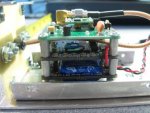
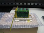
A DemoSAT was put together, basically an engineering model without solar panels and powered by batteries for a demonstration.

One picture shows it assembled inside its aluminum shell, the other the PCBs inside.

The structure has the Processor\Radio board on top, the solar panel maximum power point controller and then a supercap version of the supply board on the bottom, there is a Lithium Ion battery version also.

For an idea of scale, just left of centre on the top PCB is a black blob, that is a T092 cased power supply supervisor.
 

Attachments

fernando_g

Senior Member
What an interesting thread!
I wish that I could add my two yen, but most of the discussion so far has been on topics which are far beyond my areas of expertise.

However, after seeing the pictures, I believe I can add a meaningful comment...or maybe not....but FWIW, here it goes:

What are the g-forces you will be expecting during launch? Specifically vibration wise? There is a brownish thing on the right of the top board that looks like a ceramic resonator. Its mass and center of gravity could be two much for its tiny legs, and the thing could snap....have you tested for these conditions? Could it be better supported?

Another thing...I hope that you are applying thread locker to all screws, nuts and threaded connectors.

Lastly, that coax cable should be tied down to somewhere, don't rely solely on the solder joints to support it.
 

srnet

Senior Member
What are the g-forces you will be expecting during launch? Specifically vibration wise? There is a brownish thing on the right of the top board that looks like a ceramic resonator. Its mass and center of gravity could be two much for its tiny legs, and the thing could snap....have you tested for these conditions? Could it be better supported?
It is a resonator, and it is designed to fold over and be secured to the PCB with vacuum friendly sealant, this was as I said a demo model and its not in flight ready mode, that requires tying down of cables etc.

I should add that I am not decided whether to leave the resonator in, its not essential and no significant issues were noticed and the board was cycled from -40C to +65C. The one part of the software that could be impacted is the FSK RTTY where too much drift in the baud rate could cause decode problems on the ground, that point needs further investigation.

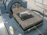
There is another engineering model over in the US that is due to be vibration tested shortly, dont expect any significant problems, there are so few components and cables in any case.
 
Last edited:

MPep

Senior Member
Of course, thermionic valves are less prone to EMP, so are in-fact a good choice for space exploration. A bit bulky though!!!!
 

MFB

Senior Member
Just finished reading an fascinating book by George H. Ludwig. Who developed the experiment for the first US satellite whilst a graduate student of Van Allen and help discover the radiation belt. The book "Opening Space Research" includes details of using early transistors and the development of an on-board magnetic tape for the next couple of satellites. Ludwig states that these first satellites seem laughably simple by to days standards and could now be implemented by a small part of the silicone used in microcontroller but it was of course quite an engineering challenge at the time.
 

srnet

Senior Member
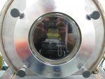
$50SAT Engineering model has survived its 'Shake and Vac' and still works !

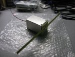
Here is the completed Engineering model, ready to fly, note the high tech dipole.

Engineering model construction carried out by a colleague on this project, Michael.
 

Attachments

srnet

Senior Member
Should have used the 24" to 36" section of the tape, I hear it gets better reception
The dipole lengths were actually trimmed for maximum radiated field strength, in order to get the match from antenna to radio as close to optimum as possible.
 

srnet

Senior Member
I did implement an EEPROM corruption test, to see how well the EEPROM tolerates the temperature cycling (+60 to -40) and particles from space.

The config for the radio is run an a regular basis, and the associated 32 bytes of config data are stored in table, and compared with the same values in matching locations in EEPROM. There is also a checksum value. Any discrepancies are recorded and sent out with the data packet.

There is a corruption check on a 512 bytes block of unused scratchpad RAM, also reported.
 

Hemi345

Senior Member
The dipole lengths were actually trimmed for maximum radiated field strength, in order to get the match from antenna to radio as close to optimum as possible.
I mean no disrespect, I was just joking with you about your high tech material choice being a tape measure for the antenna. :) I bet that came in handy to trim 1/8" at a time till you found the optimum match (or 1mm if your tape is metric... can't quite see it from the angle in the picture).
 

srnet

Senior Member
I mean no disrespect, I was just joking with you about your high tech material choice being a tape measure for the antenna. :) I bet that came in handy to trim 1/8" at a time till you found the optimum match (or 1mm if your tape is metric... can't quite see it from the angle in the picture).
And cheap too, I bought a tape measure from a local £1 shop (inches, mm, and yes very easy to trim) it provided plenty of raw material. I did quite a bit of testing over the local park, comparing the dipole with a standard 1/4wave.
 

srnet

Senior Member
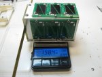
And this shows how much $50SAT weighs, destined to be the lightest working satellite in Earth Orbit.

As far as we know to date the the lightest and smallest have been the incredibly porky Cubesats.
 

Attachments

Paix

Senior Member
I always failed at getting a good contact with tape measure dipoles. Cutting was very easy. Drilling found it to be fragile and prone to cracking and I found the paint over the copper plated substrate to be tenacious, so wasn't confident on pressure contact to do the job.

I made yagis with tape measure directors and reflectors and copper tube for the driven element as a result of my inadequacy.

I did think that after cleaning, dipping into a solder pot might be a solution but decided that it was an expensive idea in the absence of a suitable pot and amount of solder or large soldering iron to test the theory. No problem buying a 50W iron if it was likely to be a winner, but not so keen if it turned out to be a bad idea.
So clues to solving the reliable contact problem would be appreciated. I do know that tape measure derived antenna elements are very popular on satellites.
 

srnet

Senior Member
So clues to solving the reliable contact problem would be appreciated. I do know that tape measure derived antenna elements are very popular on satellites.
One side of the tape had the paint removed and the tape ends were screwed to copper pads on a bit of PCB, the coax was then soldered to the PCB pads.

Perhaps not the best long term solution for terrestrial use, but fortunately there should be little (no?) corrosion in space due to the distinct lack of air and moisture.

Tape measure antennas have been used for satellites before, although I could not say which.
 

Paix

Senior Member
Delfi-C3 used them, deployed from cassettes. CP4 (6)? used them with a twin resistor thermal release, held down by fishing line I believe, and others.

Thanks for the info. It's good enough for temporary terrestrial antennas, but I don't suppose that using tape measure as an all weather antenna has much to recommend it. I remember a 1/4 wave groundplane atop a fishing pole having a bit of a flap in the breeze due to insufficient stiffness. It was nice and light though.

Not long until your big day now . . .
 

manuka

Senior Member
VHF tape measure antenna around 144MHz are indeed prone to wind flutter, but the more compact UHF types at ~433 MHz are pretty immune. The garden irrigation hose fitting & tube approach I've shown at the Instructable above makes construction a versatile breeze.

Drilling certainly can tear the tape - try punching with a nail. Use lemon juice flux to aid solder coating the exposed metal, & a very hot iron (or 2!)- a star washer will bite into the metal.
Note- sharp tape ends may need rounding to avoid accidental cuts. Stan.
 
Top