Hi Folks. Thanks to Hippy and those of you who have made useful suggestions, including code to try. This includes the guys who contact me direct, and have never posted on this forum. This thread has been linked from my pages for years, and includes valuable advice - particularly from Hippy - on things like hardware and software aspects of getting a GPS-picaxe autopilot to work - often overcoming restrictions in the picaxe system. e.g. use of the faster 8M2 chip, and faster clock rate.
Sorry if I've not managed to explain clearly enough to some of you the basics of where we are on this compass thing. The large number of enthusiastic comments obviously makes it more difficult for some to go back and find what was said before. I'll therefore repeat some of a recent posting, before giving you some later information, posted by me when talking about the many variations of a simple COMPASS.BAS test program possible ....
I'm guessing many of these software "variations" would work on a "factory fresh" HMC6352, rather than that I'm using here. I suspect the one I returned to Proto-pic for test, which worked for them, was in the same "upset" condition, but something used in their (Arduino) test rig, reset it. e.g. factory default settings. That's what I'm hoping to find out from them, or others - such as Spark-fun in USA, who make that board. As I understand it, they use the Honeywell chip (and reference the Honeywell data sheet, that reccomends 10k pull-up resistors) but their board may include the pull up resistors - protopic suggested I need not include them. I'm not, at present.
So we have two tasks outstanding:
a) confirm that the AXE024 can be used reliably with the Spark-fun HMC6352, and what the recommended software statements should be, probably similar to those below. This is best done by Rev-Ed, but they obviously need a factory fresh Spark-fun HMC6352. Off-forum communication makes me hopeful this might be done in due course. Rev-Ed are obviously in the unique position of knowing the internal I2C firmware within the picaxe chip, and so - if there are restrictions, such as timing delays needed - they will know best how to do it.
b) know how to reset the Spark-fun HMC6352 to it's "factory fresh" condition. It is thought that the factory defaults will be the same as those set by Honeywell, but of course, it is possible that they have been changed by Spark-fun, or their supplier who puts the chip onto that little board. If this "resetting" can be done from the picaxe, then it can enable experimenters to recover use of an "upset" chip. It can also be included in the setup process for programs that need to be particularly resilient. e.g. restart perfectly when solar based power supply is restored slowly, when the sun comes out.
I'm sorry that my pocket money does not extend to free-issuing HMC6352 and/or AXE024 to all of you out there, who may offer to look into these issues. Those of you who want to try "hands-on" will find it easy to order the Spark-fun direct if they are in the USA, or through Proto-pic if in the UK. The HMC6352-AXE024 does seem the neat solution to many applications that need a low power compass-operated servo. Maybe some of you will think of applications other than robot boats. e.g. my existing autopilot, without compass, has been briefly tested in the air, and could easily be tried on a land vehicle. But I'm only interested in sail-power on the water
")
That earlier APSTEER.BAS program worked nicely, and the Picaxe and compass only consumed a total of 2mA. The servo took an average of 10mA, but for some applications, maybe that could be reduced further. e.g. switching the servo off. Much lower power means interesting possibilities, for things that require long periods of operation: like many months at sea
.... OK, back to the present again. I've just ordered yet another HMC6352, so I will have another "factory fresh" compass module here. I'm confident that it will work with many of the variations tried with an "upset" chip, included the simplest one, suggested by Hippy and at least one of you. Please remember that I did get the HMC6352-AXE024-Servo to work with APSTEER.BAS after a working simple COMPASS.BAS, but with code suggested by an enthusiast that Hippy thought should not work. The code that I will try with the "factory fresh" module is as follows:
Code:
'COMPASS.BAS test for HMC6352 Compass Module with PICAXE AXE024 Servo Controller
 HI2CSETUP I2CMASTER, $42, I2CSLOW, I2CBYTE
top:
 hi2cout ("A")
 PAUSE 10
 hi2cin (b1, b0) 'w0 should now hold binary Heading 0-3590 tenths of degrees
 w0 = w0 / 10 'degrees
 SERTXD ( "  H=",#w0 ) 'e.g. H=180 for south
 PAUSE 100
 goto top
This will be without the extra 10k pull-up resistors. If it does NOT work, I will obviously try other variations, such as the one that worked before my module was "upset". If it does work, as I expect, then I will include similar code in a simpler APSTEER.BAS that should also work. Then it should not be difficult to find at least one spare input pin, to take serial data such as "Target 045 degrees" from the existing GPS Autopilot, used since early last year. Functional tests could then begin on Bray Lake, to analyse how well this solution worked, compared with one that only used the GPS. e.g. the GPS plots that you will see on my front page. This obviously includes testing of things like tilting of the boat.
This compass chip could also be a much better wind direction sensor, than that based on the Ametes chip. The Module could be put into the same enclosure as seen on
www.gpss.co.uk/ametes.htm and will not suffer from the higher power consumption. i.e. only 1mA compared with 10mA. The data could probably easily be taken via the same I2C pins. Other articles describe using more than one HMC6352. I think the guy was measuring rotation between someone's head and shoulders
The tacking logic could be put back in, within the "steering picaxe", so the 2KB memory limit would not be a squeeze either. This is just one new possibility that may open up, for next year's boat.
Note that in all of the above, we are talking about the comparatively simple process of using a "factory fresh" HMC6352. The other task is more difficult, since it relates to what is going on inside the HMC6352 rather than the picaxe. This is where useful advice is as likely to come from outside this forum, including from places such as Spark-fun or even Honeywell. However, so far, I've found mention of reset methods on other "enthusiast" forums, and there is no reason why myself, or anyone with an "upset" HMC6352 and AXE024 cannot try these reset methods.
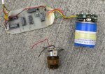
I'll put the list of links below again. Sometimes it may be quicker to look on one of my pages, than hunt back through this thread. e.g. the latest photo of the AXE024-HMC6352 without the 10k pull up resistors. However, people are often directed back into this forum if they are seeking some of the nitty-gritty of picaxe stuff.
Thanks again to everyone.
Robin
www.gpss.co.uk
www.gpss.co.uk/autop.htm - Robot boat front page including overview, latest news, videos. e.g. GPS plots towards bottom of page.
www.gpss.co.uk/rbdesign.htm - "design" page, including talk about the Compass module with picture - way past the pussy cat
www.sparkfun.com/datasheets/C...ts/HMC6352.pdf - data sheet for HMC6352 Compass Module
www.picaxe.com/docs/axe024.pdf - PICAXE AXE024 Servo Controller kit (v1)
www.picaxe.com/docs/axe024v2.pdf - PICAXE AXE024 Servo Controller kit (v2) - as used in tests above.
www.gpss.co.uk/phmc6352.gif - later picture of AXE024-HMC6352 put up several days ago.
p.s. Thanks srnet. No, I'm not using the I2C pins for servo output. But it's a useful mechanism if someone wants to "upset" an HMC6352 before testing the full reset process, still unknown. I think my more detailed post above explains this. Thanks Jeremy (below) - ref tilt errors and testing on Bray Lake: see GPS Plots on first link above - done 18 months ago. Similar test with compass would be done.
p.p.s Friday: Proto-pic bits arrived and the "factory fresh" HMC6352 was soldered onto the AXE024. As expected, the code above worked perfectly. The earlier version with the preceding "0, " also worked - as expected. A lot more tests need to be done, including with APSTEER.BAS and I'll update this post if I have more news to report.... 2pm update: Good news is that the HMC6352 that Roy returned, also now works. Maybe his Aduino rig DID do something to it good ? Also, the AXE024 he returned, also worked. So now I have two good AXE024-HMC6352 systems, and one "upset" HMC6352.
3pm update: As expected, the servo control works :
Code:
'APSTEER1.BAS based on AUTOP2TTS.BAS simple auto pilot for robot boat
'v1a 9 August 2013 for testing with rudder servo and I2C Compass Module

 #picaxe 08M2
 setfreq M16 'faster clock rate for better SERIN

 symbol CENTRE = 150 'Servo middle position
 symbol THROW = 50
 symbol LEFT = CENTRE + THROW 'Servo left
 symbol RIGHT = CENTRE - THROW 'Servo right
 symbol FOR1SEC = 4000 'pause value at 16MHz for 1 sec

 'waggle rudder servo 4 (RHS position) on startup to show that working.
 SERVO 4,CENTRE 'start servo control process - middle
 PAUSE FOR1SEC ' 0.5 sec
 SERVOPOS 4,LEFT 'move servo to position 1
 PAUSE FOR1SEC ' 1 sec
 SERVOPOS 4,CENTRE  'move servo to middle position
 PAUSE FOR1SEC
 SERVOPOS 4,RIGHT  'move servo to position 2
 PAUSE FOR1SEC
 SERVOPOS 4,CENTRE  'move servo to middle position
 PAUSE FOR1SEC


 HI2CSETUP I2CMASTER, $42, I2CSLOW_16, I2CBYTE
top:
 hi2cout ("A")
 PAUSE 10
 hi2cin (b1, b0) 'w0 should now hold binary Heading 0-3590 tenths of degrees
 w0 = w0 / 10 'degrees
 SERTXD ( "  H=",#w0 ) 'e.g. H=180 for south
 PAUSE 100

 if w0<175 then SERVOPOS 4,RIGHT endif
 if w0>185 then SERVOPOS 4,LEFT endif
 if w0>=175 and w0<=185 then SERVOPOS 4,CENTRE endif
 goto top