I have a circuit where Picaxe have 4,2-4,3V.
I have connected serial in to - and reset to + without a resistors.
Serial out is floating.
Voltage measured with oscilloscope: No spikes, it is stable.
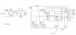
Circuit controls a motor with 2 relay (ON/OFF & COURSE).
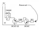
Relays have a diode to arrest a voltage spike and transistors are controlling them which are controlled by that Picaxe 18X.
I have a broblem:
Sometimes when Picaxe outputs go low and relays go to rest, picaxe goes to short circuit and blow a fuse.
If I will put bigger fuse Picaxe will get hot!
I have no idea which could arouse this condition.
I have used a two different Picaxe, so I thing bug is not in those.
I have connected serial in to - and reset to + without a resistors.
Serial out is floating.
Voltage measured with oscilloscope: No spikes, it is stable.
Circuit controls a motor with 2 relay (ON/OFF & COURSE).
Relays have a diode to arrest a voltage spike and transistors are controlling them which are controlled by that Picaxe 18X.
I have a broblem:
Sometimes when Picaxe outputs go low and relays go to rest, picaxe goes to short circuit and blow a fuse.
If I will put bigger fuse Picaxe will get hot!
I have no idea which could arouse this condition.
I have used a two different Picaxe, so I thing bug is not in those.
Last edited: