picaxe 20m2 led confusion

technokid

Member
I am creating a model railway crossing using a 20m2, but the LED's act strangely. I have a circuit that correctly receives data and pin b.0 can push 2 led's, but when I tried the same on b.1, it can only push one led. If I try to run 2 on b.1, it ignores the first LED, even though the 2 led's should be getting the same power. The LED's are in parallel, so it should run both. The only way to stop this is to have 2 led's on b.0, 1 on b.1 and one on b.2.:confused:
Please refer to my earlier thread, " picaxe 20m2 can't read more than 2 LDR's".
I am using 3mm, standard, red LED's
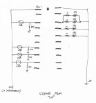
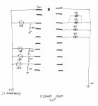
The hardware diagram is included.
I have included the software here:

Code:
TrainDetect:
b2=0
readadc C.1, b1
readadc C.2, b23
readadc C.3, b24
readadc C.7, b25
if b1<50 then goto LedFlash
if b23<50 then goto LedFlash
if b24<50 then goto LedFlash
if b25<50 then goto LedFlash
goto TrainDetect

LedFlash:
high b.7
high b.1
pause 700
low b.1
high b.0
high b.2
pause 700
low b.0
low b.2
readadc c.1,b1
readadc c.2,b23
readadc c.3,b24
readadc c.7,b25
if b1>50 then goto Timed
if b23>50 then goto Timed
if b24>50 then goto Timed
if b25>50 then goto Timed
goto ledflash

Timed:
high b.1
readadc c.1,b3
readadc c.2,b8
readadc c.3,b13
readadc c.7,b18
pause 700
readadc c.1,b5
readadc c.2,b9
readadc c.3,b14
readadc c.7,b19
low b.1
high b.0
high b.2
pause 700
readadc c.1,b7
readadc c.2,b11
readadc c.3,b16
readadc c.7,b21
low b.0
low b.2
if b3<50 then goto qwerty
if b5<50 then goto qwerty
if b7<50 then goto qwerty
if b8<50 then goto qwerty
if b9<50 then goto qwerty
if b11<50 then goto qwerty
if b13<50 then goto qwerty
if b14<50 then goto qwerty
if b16<50 then goto qwerty
if b18<50 then goto qwerty
if b19<50 then goto qwerty
if b21<50 then goto qwerty
b2=b2+1
if b2<4 then goto Timed
low b.7
goto TrainDetect

qwerty:
b2=0
goto LedFlash
Hoping someone can help explain what is going on here.
Andrey Train detector flasher.jpg
 
Last edited:

srnet

Senior Member
As a general rule I would avoid paralleling LEDs directly.

Fit each LED with their own series resistor.

If the forward voltage drop of the LEDs varies between individual devices (and it can) you can have a situation whereby one lights and the other does not.
 

Goeytex

Senior Member
As srnet indicated above, there MUST be a current limit resistor in series with each LED. The value of the resistor depends upon what color the LED is, its current rating, and how bright you want the LED to be. I used 1K resistors since we do not know what size & color they are. You could probably use 470R resistors.

If both LEDs on PIN 18 are the same color (same forward voltage) then the parallel configuration might work, however it is better to have each LED on a separate pin.

Are the LEDs 3mm or 5mm?
What color?

Attached is your schematic corrected to add the resistors.
 

Attachments

John West

Senior Member
LED's aren't really properly driven by voltage, but by current. The voltage drop across an LED changes with its temperature, so current is used as the controlling parameter. As most drive sources in electronics are designed to regulate voltage and not current, additional circuitry is typically necessary to control LED's. This may be something as simple as a ballast resistor for low powered LED's, or may need to be more complex for high-powered LED's.

The easiest way to get the same current through 2 LED's is to put them in series. Then they are forced to see the same current. However, a lot of power sources are limited to 5 Volts or even less, while most LED's drop enough voltage that putting 2 in series doesn't work with a simple ballast resistor. Not enough total voltage to play with. When I need to run 2 (or 3) LED's in series I try to come up with a 12 Volt source to drive them.

On a PICAXE project without a higher voltage available, I'd put one LED and 1 ballast resistor on each of 2 PICAXE outputs.
 

technokid

Member
Do you mean to use the 20m2 to trigger a bc547 transistor or similar to supply the 12 volts, like this?
Copy of Relay Driver.jpg
 
Last edited:

inglewoodpete

Senior Member
TK, As others have suggested before, you need a resistor in series with each LED. You should be able to drive two of these with one output pin of a PICAXE.

Leaving the series resistor out risks damaging the PICAXE chip.
 

Goeytex

Senior Member
Two 3mm LED's wired in series can be driven directly from a Picaxe output pin (assuming a 5V supply to the Picaxe). But again, a current limit resistor must be used. A 12V supply with a transistor and the appropriate resistors will also work, but should not be necessary with two 3mm LEDs.

A red LED will be brighter than a green LED given the same supply voltage and same current limit resistor. This is because the RED led has a lower forward voltage and will conduct sooner than a green LED. So to keep the brightness levels relatively even, a larger resistor is needed for the Red LED circuit.

Attached is a graphic that shows some possible good configurations, and some not so good ones.
 

Attachments

Top