PICAXE-08M layout change - or fault ?

Robin Lovelock

Senior Member
Hi Folks. Here is an email just sent to the orders guys. I think it is self-expanatory. Hopefully they will give me an explanation soon.

To <tech supplies email> ref invoice 14246-1 for picaxe-08m servo driver £10.80

Thanks for the prompt delivery - but it seems this batch of picaxe-08m may be faulty.
Has the layout of the picaxe-08m servo driver changed ?
Maybe this batch have the artwork on the PCB printed the wrong way round ?

I have built several of these in the past 2 years and had no problems.
Today I carefully soldered together the kit you sent, following the artwork
on the circuit card for where components are placed.
When powered up, the unit did not function and the chip got hot.

I then saw that the artwork seemed to be the wrong way round,
resulting in components being assembled as a mirror image.
Not surprising it did not work and got hot :)
Pretty amazing that holes were in the right place for this to happen.

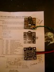
I attach a photo showing:
1) one of my old picaxe boards
2) the picture on your documentation matching it
3) the new board from you - but the underside - showing layout is wrong.

I would appreciate a replacement kit and explanation.
Many Thanks in advance.

Robin Lovelock
 
Last edited by a moderator:

Andrew Cowan

Senior Member
Hi Robin

Could you upload the images to the forum? I'd be interested to see them.

I assume that you inserted the components on the right sde of the board - the silkscreen side (with the white writing) should be the side the components are entered from.

A
 

westaust55

Moderator
IMHO, having only JUST sent Rev Ed orders dept a query, I would have thought you might have given Rev Ed time to reply before going public and calling "foul"
 

Technical

Technical Support
Staff member
We'll respond with the photo sent to us. It needs no further comment, as Andrew got there first!

We've also deleted your personal info from your forum post.
 

Attachments

Robin Lovelock

Senior Member
And the Internet has a long memory ......
Indeed - yes, I have a very red face. Good to see how many replies there were to this posting, in the hour or two I was out of the house :)
It seems I did not make this silly mistake on all my other boards - silly me.
Robin
p.s. I'm quite relaxed about my full contact details being public
- they have been for over 15 years - www.gpss.co.uk

This reply just sent >>>

How embarassing - I can see you are correct :)
Robin

On 13/04/2011 13:17, PICAXE Support wrote:
> Thanks for your email.
> However you have incorrectly assembled the boards by soldering on the wrong side.
>
> Regards
>
> Technical Support
>
 

hippy

Ex-Staff (retired)
Hands up all those who haven't wired or soldered up a jack, XLR, or other plug or socket and then wondered how to get its cover onto the wire without re-doing it all again :)

Those with their hands up will likely be able to put them down at some time in the future.

Rubber mains plugs often catch me out as the covers can't always be fitted afterwards as plastic plug covers can.
 

inglewoodpete

Senior Member
Back to original subject: it may be possible to remove the PICAXE socket and the 3.5mm socket and put them of the correct side of the board. At least the servo driver would work (and be unique!)
 

Andrew Cowan

Senior Member
The reason I thought of the problem so easily was after seeing a PICAXE datalogger board at school, where everything had been soldered on the wrong side. With through plated holes, it's very hard to desolder multi lead components such as an IC socket - at least you screwed up on a low cost board!

If you do decide to try and fix it, obviously some components (power leads, servo headers, resistors, capacitors) can be left in place.

Andrew
 

inglewoodpete

Senior Member
I've found the best way to remove multipin devices from a PCB is first to firmly support the board upside down (in this case, the right way up :)), so the offending part can fall out.

Ensure your soldering iron tip is well tinned (use a bigger tip or iron if you have one). Work quickly so that components don't get damaged. Rather than use solder wick, pile on additional solder with the tip parallel with the board. The additional solder will stay molten longer, giving you a chance to have all pins in liquid solder at once. The chip or other component will usually fall off the board.

It's a particularly good method for SMD components but also works for through-hole ones as well. I haven't had a chip fail using to this method yet but often they're already faulty.
 

hippy

Ex-Staff (retired)
Assuming the PICAXE is socketed, you can unplug that, then snip between the legs of the socket allowing each pin to be removed individually. That's usually far easier than trying to remove the socket in one go and you only waste the cost of the socket. The jack socket is low cost as well so if that's damaged it's not the end of the world.
 

clockwork

Member
Robin may be lucky and has only destroyed one cheap picaxe chip.

I managed destroy a PC power supply by not realising it required some form of load to operate when I was testing it out of the PC case. It made a good bang when it went!

Best B***s up happpened to a friend who just happened to be a Senior Marconi Marine Engineer at the time. he homebrewed a 30 amp 12v power supply (for amateur radio use)
However he managed to reverse the connections on the two very very large(about 10" tall by about 5" across) smoothing capacitors, (this was before switch mode power supplies were introduced). The net result was a VERY VERY LARGE BANG when both capacitors literally exploded leaving his living room covered in very small bits of whitish paper. It looked like it had snowed.

So Robin dont worry, we have all done it, but not everybody admits it.
 

srnet

Senior Member
Back around 1980 I saw the cremation of a very new and very advanced 68000 proccessor board (for the time).

It was being used as a graphics generator in an amusement machine, and the monitor was one of those types that was live to the mains, it needed to be used with an isolating transformer on its mains supply.

Dont ask who forgot to use the isolation transformer.
 

techElder

Well-known member
I just knew this was going to be a really good April Fool's joke ...


... but, dang it! Just turned out to be a note from the diary of one of the thousands of electronic technicians out there.
 

Robin Lovelock

Senior Member
Thanks Martin. I must admit that I spent a few minutes trying to unsolder, then decided it would be quicker to order a new board, which I did yesterday. It arrived promptly this morning - less than 24 hours - and of course, when I soldered the components in on the CORRECT side - it worked first time - just like all the others.

I'd love to say that this thread was a "deliberate mistake" on my part - which of course it was not - but it did confirm my high opinion of how quick, low cost delivery of the PICAXE products is backed up by even faster excellent technical support.

So my red face was worth it :)
Robin
www.gpss.co.uk/autop.htm - the transatlantic robot boat page. Enjoy the videos :)
 
Top