Jeremy Harris
Senior Member
First off, a safety warning. This is NOT a project to be attempted by anyone who doesn't understand the risks of working with mains voltages. If you aren't competent at building a circuit that includes mains voltage wiring DO NOT attempt to build this.
OK, now I've (hopefully) allayed the concerns of the more safety conscious members, let me explain what this unit does, and how it works. In the UK, anyone with a solar photo voltaic (PV) system may receive a Feed In Tariff (FIT) subsidy, paid on the basis that 50% of their installed PV capacity will be exported. There is therefore a financial advantage in using as much of the power you generate as possible. One way to do this usefully is to divert any excess power generated to an immersion heater, to help heat the hot water tank. With a big hot water tank you can store a fair bit of hot water and in summer can probably get all your hot water for free using such a device.
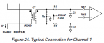
Commercial units are available, but they cost between £200 and £300 as a minimum; one even sells for well over £1000. The challenge was to find a way to accurately measure the power being used by the whole house, and accurately determine whether power was being imported (from the grid to the house) or exported (from the house to the grid). Luckily, there are some very cheap and accurate electricity meter front end chips available that do all the hard bits. These use an isolated clip-on current transformer to measure the current flowing in the main feed cable to the house (the cable from the meter) and an isolating mains transformer winding to measure the supply voltage, and can calculate the true power (allowing for power factor variations) and output a frequency that is proportional to power and a direction signal that indicates import or export.
These two logic signals can be easily read by a Picaxe, so the next challenge is to work out how to control an immersion heater (safely). Luckily, fully isolated Solid State Relays (SSR) are readily available at a reasonable price (I paid £6 for a surplus 25A Cruezet one). These are easy to use and will switch a big mains load safely at the zero crossing point directly from a Picaxe output pin, as they have a built in opto isolator. The difficulty was finding a way to vary the power sent to the immersion heater, so that it was just enough to use any surplus, but not so much as to end up having to pay for imported electricity.
The market leading commercial device just uses burst fire control of a triac (which is what's inside the SSR) to effectively vary the number of on and off cycles of the mains to vary the power to the immersion heater. This works, but has a side effect that has attracted some criticism. Under some conditions this rapid switching can cause lights to flicker, not only in the house with the unit fitted, but also in the homes of close neighbours. It's not a major problem, but not that desirable, either. Luckily a chap on the Open Energy Monitor forum, Robin Emley, has come up with a way around this problem, using a method that doesn't need resorting to a potentially nasty control method, like phase angle control.
Robin's technique utilises a deliberate design feature within electricity meters. To ensure that these meters don't "creep" when no power is being consumed (due to small measurement errors) they have a threshold energy level below which they don't register. This is usually set to around 1 Wh, or 3600 Joules. If less than 3600 J is imported from the grid the meter won't record it. This means you can "borrow" up to 3600 J from the grid and send it to the immersion heater, then "repay" this with the same amount of energy exported back to the grid, so resetting the meter energy threshold.
As the meter front end chip supplies accurate power and direction data, all the Picaxe needs to do is manage an "energy bucket", monitoring when the bucket reaches a set level of exported energy, then turn on the immersion heater and wait for the bucket to empty to a set minimum level. I've set the "energy bucket" to have a capacity of 3600 J and have set the immersion turn on threshold to be 75% of this and the immersion turn off threshold to be at 25%. To eliminate an accidental drift towards importing energy, the "energy bucket" has a small leak, so that over time it will tend to empty, even with the immersion heater turned off.
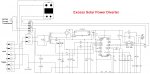
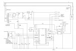
This project uses an 08M2 as the controller, and an Analogue Devices AD7755 24 pin DIP meter front end chip (unfortunately this particular chip has now been discontinued, but there are very similar alternatives available). Below I've given details of the circuit and construction, together with the code.
As mentioned at the beginning, this is NOT a project to be undertaken by anyone who isn't competent with mains voltages. Although the design is safe, this project requires an understanding of isolation and earthing and an acceptable level of competence in assembling mains voltage circuits. It is NOT suitable for construction using strip board or prototype board construction methods. Finally, if you decide to build a unit like this, then I take no responsibility for your own safety.
OK, now I've (hopefully) allayed the concerns of the more safety conscious members, let me explain what this unit does, and how it works. In the UK, anyone with a solar photo voltaic (PV) system may receive a Feed In Tariff (FIT) subsidy, paid on the basis that 50% of their installed PV capacity will be exported. There is therefore a financial advantage in using as much of the power you generate as possible. One way to do this usefully is to divert any excess power generated to an immersion heater, to help heat the hot water tank. With a big hot water tank you can store a fair bit of hot water and in summer can probably get all your hot water for free using such a device.
Commercial units are available, but they cost between £200 and £300 as a minimum; one even sells for well over £1000. The challenge was to find a way to accurately measure the power being used by the whole house, and accurately determine whether power was being imported (from the grid to the house) or exported (from the house to the grid). Luckily, there are some very cheap and accurate electricity meter front end chips available that do all the hard bits. These use an isolated clip-on current transformer to measure the current flowing in the main feed cable to the house (the cable from the meter) and an isolating mains transformer winding to measure the supply voltage, and can calculate the true power (allowing for power factor variations) and output a frequency that is proportional to power and a direction signal that indicates import or export.
These two logic signals can be easily read by a Picaxe, so the next challenge is to work out how to control an immersion heater (safely). Luckily, fully isolated Solid State Relays (SSR) are readily available at a reasonable price (I paid £6 for a surplus 25A Cruezet one). These are easy to use and will switch a big mains load safely at the zero crossing point directly from a Picaxe output pin, as they have a built in opto isolator. The difficulty was finding a way to vary the power sent to the immersion heater, so that it was just enough to use any surplus, but not so much as to end up having to pay for imported electricity.
The market leading commercial device just uses burst fire control of a triac (which is what's inside the SSR) to effectively vary the number of on and off cycles of the mains to vary the power to the immersion heater. This works, but has a side effect that has attracted some criticism. Under some conditions this rapid switching can cause lights to flicker, not only in the house with the unit fitted, but also in the homes of close neighbours. It's not a major problem, but not that desirable, either. Luckily a chap on the Open Energy Monitor forum, Robin Emley, has come up with a way around this problem, using a method that doesn't need resorting to a potentially nasty control method, like phase angle control.
Robin's technique utilises a deliberate design feature within electricity meters. To ensure that these meters don't "creep" when no power is being consumed (due to small measurement errors) they have a threshold energy level below which they don't register. This is usually set to around 1 Wh, or 3600 Joules. If less than 3600 J is imported from the grid the meter won't record it. This means you can "borrow" up to 3600 J from the grid and send it to the immersion heater, then "repay" this with the same amount of energy exported back to the grid, so resetting the meter energy threshold.
As the meter front end chip supplies accurate power and direction data, all the Picaxe needs to do is manage an "energy bucket", monitoring when the bucket reaches a set level of exported energy, then turn on the immersion heater and wait for the bucket to empty to a set minimum level. I've set the "energy bucket" to have a capacity of 3600 J and have set the immersion turn on threshold to be 75% of this and the immersion turn off threshold to be at 25%. To eliminate an accidental drift towards importing energy, the "energy bucket" has a small leak, so that over time it will tend to empty, even with the immersion heater turned off.
This project uses an 08M2 as the controller, and an Analogue Devices AD7755 24 pin DIP meter front end chip (unfortunately this particular chip has now been discontinued, but there are very similar alternatives available). Below I've given details of the circuit and construction, together with the code.
As mentioned at the beginning, this is NOT a project to be undertaken by anyone who isn't competent with mains voltages. Although the design is safe, this project requires an understanding of isolation and earthing and an acceptable level of competence in assembling mains voltage circuits. It is NOT suitable for construction using strip board or prototype board construction methods. Finally, if you decide to build a unit like this, then I take no responsibility for your own safety.
Code:
;Energy bucket immersion heater PV diverter, using Picaxe 08M2 controller

;Code not yet fully tested, but does seem to work as expected using a bench simulation

;Uses Analog Devices energy meter chip, AD7755 (now replaced by ADE7755, only available as surface mount)

;AD7755 determines true instantaneous power and direction of energy flow and has two outputs
;Output CF is an 18µS wide positive pulse equivalent to 10 J that has a PRF of between 0 and about 5570 Hz (covering a range of 0 W to 55.7 kW in theory)
;Output REVP indicates the direction of energy flow, low for import, high for export

;Operating Principle:
;
;Uses interrupt to trigger a routine whenever a CF pulse occurs.  This interrupt is on pin c.3 and is set up using the setint command (pin and mask)
;The state of the REVP input (pin c.3) is used to determine whether 10 J is added to the energy bucket or whether 10 J is subtracted from it.
;A small safety leak is built in, in that after a set number of iterations of the interrupt routine the energy bucket accumulator is decremented.
;the loop counter used to keep track of the number of iterations of the interrupt routine is reset to 0 after the leak is decremented
;The energy bucket accumulator has a lower limit of 0 J and an upper limit that is set by the variable "capacity", in Joules / 10
;When the energy bucket accumulator fills to the upper trigger level, set by the value of "upper", the solid state relay is turned on, via pin c.2
;Whenever the energy bucket accumulator empties to the lower trigger level, set by the value of "lower", the solid state relay is turned off
;After the interrupt routine has completed the setint command is used to "re-arm" the interrupt, ready for the next energy pulse
;
;With values of 270 for the upper trigger point and 90 for the lower trigger point this controller shuttles 1800 J across the meter
;The majority of household energy meters have a 1 Wh (3600 J) threshold before registering any energy.

;This design reduces the flicker frequency by offsetting the upper and lower trigger points.  Typically the immersion will turn on for a short period every few seconds.
;For example, at 500 W export the immersion will be on for 0.7 seconds and then off for 5.5 seconds, with a 2% leak rate set.


;Pin designations:

; pin c.4 = CF		pulses from AD7755, calibrated to be 10J per pulse

; pin c.3 = REVP		import/export direction signal from AD7755.  High for export, low for import

; pin c.2 = output to drive SSR, high is SSR on, low is SSR off


#picaxe 08M2


symbol accumulator = w0										;energy bucket accumulator variable

symbol leakcounter = b2										;used as loop counter for leak, records number of times interrupt routine called

symbol upper = 270										;upper energy bucket threshold for switching on immersion (270 = 75% full)

symbol lower = 90											;lower energy bucket threshold for switching off immersion (90 = 25% full)

symbol capacity = 360										;nominal 3600 joule energy bucket capacity (value = Joules / 10)

symbol leak = 50											;50 gives a 2% leak rate in the energy bucket (decrements by one every 50 iterations)


init:

	setfreq m32											;set clock frequency to 32 MHz for best speed

	setint %00010000, %00010000								;set interrupt on pin c.4, masked to detect high pulse


main:

	pause 1000											;loop around aimlessly waiting for an interrupt
	goto main


interrupt:												;interrupt routine is called whenever an energy pulse is detected

	inc leakcounter

	if pinc.3 = 1 then let accumulator = accumulator + 1 max capacity		;accumulate export energy in energy bucket up to max set by variable "capacity"
	endif												;pin c.3 is REVP on AD7755 and indicates import/export
													;pin c.3 low = import, pin c.3 high = export
	if pinc.3 = 0  then let accumulator = accumulator - 1
	endif

	if accumulator > capacity then let accumulator = 0				;trap under flow error from subtracting from zero
	endif

	if accumulator > upper then high c.2						;switch on immersion if over upper trigger level
	endif

	if accumulator < lower then low c.2							;switch off immersion if below lower trigger level
	endif

	if leakcounter = leak then
		let accumulator = accumulator - 1 min 0					;decrement accumulator once every "leakcounter" times interrupt called
		leakcounter = 0
	endif

	setint  %00010000, %00010000								;re-arm interrupt ready for next energy pulse

	return											;return back from interrupt routine to main loop

													;interrupt routine takes about 950µS to execute

END
Last edited: