Pb switchmode charger/discharger.

BeanieBots

Moderator
Switch mode Battery Charger. (code & circuit in post #2)

This project started off as a simple bi-directional battery capacity meter. This was at a time when there was a lot of chat about MPPT controllers and using PICAXE to control switchers. To prove the point one way or another, I decided to add the required bits to the project in an attempt to make a switching MPPT controller. After quite a bit of persistance, I eventually gave up and concluded that it was not possible using the PWM function directly because the resolution was not fine enough. The hunting on the input side was too great to offer any real benefit. However, I still had several days labour invested in the hardware which I did not want to go to waste. I decided to convert it into a bi-directional battery charger/discharger. This has proved to work really well.

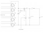
I'd like to point out the sole purpose of the excersise was to prove/disprove by actually building and testing how well a switcher would work by connecting the FET directly (actually via a low value resistor) to a PICAXE PWMout pin. No FET drivers and no other means of PWM control. So please, no "theoretical" comments about how bad the design is. I'm fully aware that it's bad practice. I wanted to PROVE how bad (or good) that approach would be. Or even if it's possible as so many people seem to want to try it and so many others want to shoot them down in flames for trying. The FET is a IRF520 and the flyback transformer is self wound 27:23 on an RM8 core with air gap. The only other semiconductors are an LM324 bog standard quad op-amp, a 78L05 voltage regulator, a BC237 tranny, a 1N5821 Schottky for the switcher, an MUR160 for the snubber and a few other diodes.

Anyway, I could go on for ever about the why's and why nots but I won't unless somebody specifically asks.
As mentioned, the original hardware was for just a capacity meter, hence I used what seemed an appropriate PICAXE at the time, namely the 18X. When I finalised the battery charger/discharger design, it proved to be a little short in both I/O and program space so I couldn't squeeze in all the features I wanted. If anyone can see a way of reducing the code size by enough to add some more features I'd be very pleased. I could take out things like the "beep" for each button press but that alone would not be enough to add another menu item.

Without further rambling, here's the final project spec and functionality.

Functionality:-
User selectable cycle of:-
a) Charge only
b) Charge : Rest : Discharge
c) Charge : Rest : Discharge : Charge
d) Discharge : Charge
e) Discharge only
f) Hold at voltage for indefinite period.

Functional description:
The amp hours transfered at each stage are measured and saved to EEPROM for recall later.
The charge cycle charges at a user configurable constant current up to a user configurable BULK charge voltage.
Once the BULK voltage has been reach, the controller switches to constant voltage mode and holds the battery at that voltage until the current reduces to half of the user defined constant charge current. The charger takes note of how long it took to get to those conditions. It then enters float mode. It will stay in that mode for the same amount of time it took to do the bulk charge. Whilst in float mode, the battery voltage is maintained at an independant user configurable FLOAT voltage whilst not exceding the same maximum current used in BULK mode. Once the time has elapsed, the charge process is deemed to have completed. The BULK phase has a maximum timeout period of 8 hours to prevent dead or sick batteries from being cooked even further. Thus, the maximum possible charge cycle is limited to 16 hours.

The discharge phase discharges at a user definable constant current until a user definable cut-off voltage is reached.

If the only or last phase is a charge cycle, once the charge is complete, the controller enters hold mode.
In hold mode, the controller will hold the battery voltage at yet another user definable "HOLD" voltage indeffinitely. Current is limited to the current set for the charge cycle.

If a charge cycle is followed by a discharge, there is a 20 minute rest before the discharge starts. I would have liked to make the rest period user configurable but there was not enough program space. The rest period can be aborted during operation with a simple button press.

I am not convinced that the BULK to I/2 followed by FLOAT for same period is ideal. I'm open to suggestions on that one.
All voltages and currents are user configurable. I've in no way tried to impose my Pb beliefs. It's entirely up to the user how they choose to destroy their batteries.

Take note that during discharge, power is reversed and flows from the battery back to the supply. So, don't use a wall-wart or it will blow up. The supply must be a larger battery or clamped voltage source. Also, if the battery is diconnected during a charge, the controller will still try to supply current. Current into an open circuit builds up voltage VERY quickly. Too quick for a PICAXE to control. For that reason, one of the op-amps is configured as a comparitor for emergency shut-down should the converter go over-voltage. It is connected directly to the converter output and hence works for both charge and discharge. It is also on the converter side of the fuse for obvious reasons.

Continued in next post.......
 

Attachments

Last edited:

BeanieBots

Moderator
Continued....

Technical spec:
You will often see power supply specs for line/output regulation and output/load response measured in mV and mS.
Well this does not have little numbers anything like those. It is measured in full blown VOLTS and SECONDS.
It is NOT a power supply and never could be.
It takes about 10 seconds to get up to working current. If a fully charged battery is put on charge, it will over/under shoot by about 0.5v several times before settling down. This does not happen when the battery presents a reasonable current load.

Voltage is measured using a true differential amplifier with offset. The leads which connect to the battery are co-axial. The braid carries the current and the core connects to the differential amplifier. This allows accurate measurement of the battery terminal voltage rather the volt-drop down the cable.
The range of the amplifier is about 7v covering about 9.00v to about 16.00v depending on component tollerances.
When read using 10 bit conversion that gives better than 0.01v resolution. After software calibration the overall voltage error is less than +/-0.01v

Current is measured using a 0.15R sense resistor. This is fed to a high gain amplifier with offset to give 0v to 5v for -1.2A to +1.2A. After 10-bit ADC conversion and software calibration, this results in a resolution and accuracy of about +/-2mA.

Controller accuracy:
When a battery is being charged or discharged, it has a fairly low impedance. That means that current can vary by quite a large amount for very little change in voltage. For this reason, once in constant voltage mode, the controller can maintain battery terminal voltage (remember the remote sense wires) to within +/-0.01v.

Current control however is another story. The bulk of the 'control' portion of the PWM signal is over a very narrow range. This results in much poorer current control. The best I could I achieve was around +/-2%. In addition to this, the original spec was for a much higher current and so the gain of the current amplifier is not ideal and wastes some of the ADC resolution. To prevent excessive hunting of the control loop, I have used a current control hyterisis of -1.5% and +3% giving an overall accuracy of about 5% after calibration.

Capacity measurement accuracy:
The PICAXE can only see the current to +/-2mA and control to it to within 5%. For this reason I have used an analogue method of measuring the capacity. The method uses a bi-directional resettable analogue integrator. Each time the integrator approaches saturation, the PICAXE resets it and counts the number of times it needs to perform a reset. Hence, accuracy and resolution are defined by the quality of resistors used, the stability of the integrator capacitor and the precision of the reset pulse sent by the PICAXE. It is of course also subject to how well it's calibrated. To explain the full story would be beyond the scope of this article. Suffice to say it's around +/-3% which is a whole order of magnitude better than it would be if the PICAXE simply measured the current and accumulated it over time. Not to mention the problem of getting the PICAXE to measure time AND do all that is required to control the converter! With good setup it is possible for the integrator to resolve to better than +/-10uA !

User configurables:
Bulk voltage 12.50v to 14.60v in steps of 0.1v
Float voltage 12.50v to 14.60v in steps of 0.1v
Hold voltage 12.50v to 14.60v in steps of 0.1v
Cut off voltage 9.50v to 13.80v in steps of 0.1v

Charge current 50mA to 700mA in steps of 50mA
Discharge current 50mA to 700mA in steps of 50mA

The user interface is an AXE033 2X16 serial LCD and two illuminated pushbuttons. The second pushbutton shares its input with the EMO signal. Pushing it during a program cycle will enable a manual abort to take place. Unfortunatley, because they both generate the same signal, it is not possible to distinguish between a deliberate abort or a fault generated abort.
There is also a peizo buzzer. This sounds for each button press as an acknowledgement. I also make it do very breif little 'tick' each time around the control loop for comfort that it's actually running. It does a BEEP at the and of each stage inclusing the transition from BULK charge to FLOAT charge.
The buttons are labelled A and B.
During a charge, button A is lit. The display shows "B" during BULK and "F" during FLOAT. The capacity, current and volatge are also displayed. In the BULK phase, the elapsed time is shown in minutes and counts up. In the FLOAT phase, the remaining time is shown in minutes and counts down.
During a discharge, only the capacity current and voltage are displayed. Both buttons are lit.
During a final charge, the display is the same as a pre-charge except button B is lit.
At the cycle end or during a "Hold", button B flashes. The use of the illuminated push buttons gives "at-a-glance" indication of what the controller is doing.

At first power up or after the end of a cycle, the user is presented with.
"Press A to start","B to review results".
If B is pressed, the results of the previous run are cycled on the LCD.
The EEPROM results show capacity during each phase.
"P" for the pre-charge, "D" for discharge, "E" for End charge and "H" for any capacity accumulated during "Hold".
Pressing A will take you back to the start.

If A is pressed, the currently selected program cycle is displayed. Pressing B will move to the next program cycle, pressing A again will select the shown program and move on to display the current user defined settings. Only those settings applicable to the selected program are displayed.
Pressing B will increment the user setting. If B is held down for more than about 1S, the setting is automatically incremented at a high rate until the maximum is reached when it is reset to the lowest value and continues to increment.

The biggest challenge with this project was getting all the settings user configurable with just two buttons and making it all fit into an 18X. I would be very pleased to receive comments on a better way of doing it.

In conclusion:
With the caveat of direct connection between PICAXE and FET using Flyback topology.

It is NOT possible to make a MPPT controller.
It is NOT possible to make a power supply.
It IS possible to make a respectable battery charger.
It is not practical to transfer more than about 10W.

In the mid current area, the charger is >80% efficient (>85% for the switcher alone). The FET does not even get warm.
At lower currents efficiency drops off with the circuitry quiescent current being the most significant cause.
At higher curents, the I^2.R losses become more significant but the limiting factor is that the IRF520 is only driven by 5v and cannot pull to its maximum ability. Also, core saturation starts to come in making it run away and efficiency drops off very rapidly.

What's next.
Try again using 28X1. More buttons for user input, more display (4X20 min).
Run at 16Mhz for faster PWM. Use a totempole FET driver.
Use proper low ESR caps. Maybe active rectification.
Try Forward converter topology. (Less sensitive to PWM variation).
Goal, 50W @ 90%. PICAXE still doing PWM, keep with simple easily sourced hardware.

For those of you remotely interested, the code is attached.
To make it more readable in the editor, use a tab space of 3.
 

Attachments

Last edited:

boriz

Senior Member
WOW COOL!

Not yet convinced MPPT is impossible with Picaxe though. Remember you said in another thread that you wanted people to contribute code ideas for MPPT? Well I had an idea but was waiting until you started your MPPT thread.

You indicated that you were using a simple feedback method to track the peak. Increase duty, check the output current, if it’s greater, increase duty again, if it’s lower, decrease duty and repeat. Is that right?

The MPPT curve, for a particular panel, for a particular sunlight condition is roughly like a hill. It has a peak that slopes off on both sides. As the sunlight conditions change, the curve moves around the ‘graph’ in the Y and the X, but always retains roughly the same shape.

My idea is to use two duties. Both equally spaced on either side of a virtual centre duty (D0). Let’s say D- is 5% less than D0 and D+ is 5% greater than D0. The feedback routine follows this sort of logic:

Set duty to D- and measure output (O-)
Set duty to D+ and measure output (O+)
If O- < O+ then you are on the left hand side of the slope, increase D0
If O- > O+ then you are on the right hand side of the slope, decrease D0
Repeat

Most of the time, the duty should be set to D0, and the above process is called (say) every few seconds. If the difference between O- and O+ is below a certain ‘tolerance threshold’ then no change is made.

What do you think?
 

BeanieBots

Moderator
Boriz,
Nothing wrong with your theory and MPPT control is possible with a PICAXE but NOT if the PWMout from the PICAXE is used to control the gate of a FET using flyback topology.

The problem relates to the resolution of the PWMout command.
Flyback is probably the worst topology to use (in this insatnce) because it should not be driven driven beyond 50% which makes the problem worse. Also, being a predominantly voltage driven system (similar to a forward converter), a significant duty is required just to get the output up to "working" voltage. To compound the problem even further, when driving a load such as a battery (typical load for a MPPT), the output impedance 'sees' a very low load impedance. Once in the power transfer phase, the transfer function is a square law which even further compounds the problem.

I don't have the ACTUAL numbers to hand that came from my results but this example explains the problem.
Suppose that a duty of 30% makes the MPPT run at it's optimum. Let's say about 80% efficient.
A duty of 29% would hardly load the panel at all and efficiency would drop off dramatically. A duty of 31% would excessively load the panel again resulting in a MASSIVE drop in efficiency. Now let's say the battery gains a little charge and the optimum duty would be 30.01%. Running at 30% would only give about 50% efficiency and running at 31% would give only about 30% efficiency. The PICAXE is simply not capable of running at the required duty to give a better efficiency than just connecting the panel direct.

I had a half hearted attempt at introducing a derivative term into the control loop to try and dither the duty between two values but the loop bandwidth was not fast enough to make it work. I'll admit that using larger magnetics a faster PICAXE (28X1) and a tighter loop with a better derivative algorythm MIGHT work but the calculations required don't lend themselves to a tight loop so I don't see the point in trying.

If we take out the caveat of PICAXE PWM driving the FET, then obviously any valid MMPT algorythm can be made to work and I've done that with several different methods.

What was really interesting about this excersise was that the "expected" problems (eg no FET driver)were NOT an issue and the "KILLER" (PWM resolution) was not even anticipated. But then I'm an analogue design engineer and don't have to deal with quantisation problems on a daily basis;)
 

Janne

Senior Member
Now this is an interesting topic. As previously quoted, the MPPT funktion for solar battery charging is indeed rather hard to do.

I've had a different MPPT idea lying around for a while. I have a project wind turbine, that is used for battery charging. In wind turbine, the biggest challenge is to get the turbine to run at it's peak power RPM.

The idea I've in my head would consist of an anemometer, and current feedback loop. I would then load some predefined start values for the mppt for each step in the controller, say maybe every 0.5m/s values. Then, in steady wind the controller would make use of the mppt funktion to try higher and lower values to see if it would improve performance.

I have a feeling this system would be far less prone for suffering from small variations in the pwmout than the solar panel system.
 

BeanieBots

Moderator
The PICAXE PWM issue is a function of how smps work. The MPPT algorythm is not really part of the problem so it won't make any difference what the power source is. The issue is delta_power_out vs delta_PWM_duty. It's quite simply, too course.

I've done very little work myself on wind turbines so I do not feel I am qualified to make any remarks on that subject but you WILL have the same problems with a switcher that uses 10-bit resolution covering 0-100% duty using a flyback or forward converter. A buck will be the least sensitive.
 

BeanieBots

Moderator
Correct, the output of a buck is virtually proportional to duty.
Still bad if you do the sums but not as bad as flyback.

EDIT:
I've just thought of an analogy to this.
It's a bit like trying to do up a nut and bolt to the correct torque using a ruler to measure the distance between the nut and bolt head when the ruler is scaled to cover the full length of the bolt. The PWM is scaled from 0% to 100% but zero to max current is over a very small range, just like zero to max torque for the nut is over a very small distance. The different switcher topologies is like the nut/bolt being made of different materials.
A forward converter into a battery is like a nut/bolt made of glass.
A buck converter is like a mild steel nut/bolt.
 
Last edited:

Janne

Senior Member
Hello again.

I made a little draving of what I've been thinking. i guess this is the one called buck converter.

So first the AC input from the turbine is of course rectified, and then fed to a large capacitor, to get rid of spikes caused by the generator inductance.

After that is a fet, hopefully controlled by picaxe pwm duty, that is feeding the battery through a large inductor, to help keep switching frequencies small enough not to cause overwhelming problems. The schottky diode is there to provide a path for the current when the fet is turned off.

I've never designed or built a switch mode converter before, and I feel it's still going to be a little while more research before I'm comfortable trying it. But with this design, like stated above the current should be proportional to the duty cycle.

edit: the component values are just something thrown off from hat, so they propably are not correct.
 

Attachments

Last edited:

BeanieBots

Moderator
Nothing wrong with the overall scheme and the components are in the right ball-park. I'd suggest a lowish value resistor between the NPN collector and FET gate for safety and reduced transisents.

Your input cap looks a bit small (assuming you meant 100uF).
A bit large if you meant 100mF (milli-farads!)

What is the overall power rating?
What switch frequency do you intend to use?
No output cap.. what is your permissable ripple on the battery?

If you have never built a switcher before, there are a lot of things to consider. In particular, layout.
Before starting the design, you need to know the answer to my questions. Then you can start calculating component values. In particular, the inductor size and value will be determined largely by the maximum possible output current and the switching frequency. Alternatively, you can start with an inductor and work backwards but at some point, you need to make some descisions and then design around those descisions.

You will also need appropriate voltage monitoring dividers, current sense and few other bits & bobs but the concept is there.
Note, for max PWM resolution, f=3.9kHz at 4Mhz clock.
 
Last edited:

Janne

Senior Member
Hello BB, and thanks for your input.

The maxium peak power of the wind turbine is about 800W, meaning a maxium output current of about 60A into a 12V battery. On the switch frequency i intented to stick to some low value, from what I've gathered the layout and other issues became much more of a problem in high switching frequencies. The 3.9kHz might be a good starting point for the design.

For the input cap i really meant 100mF (millifarads).. after reading a bit of this page
http://powerelectronics.com/power_systems/dc_dc_converters/power_buckconverter_design_demystified/index.html
i noticed that it would be way overkill. something in the range of 1-2mF should be more than plentiful. One thing i didn't guite figure out, is that could one use an electrolytic cap for the input capasitor? The required ripple current seems high, i wonder if they would cope with it. I couldn't find any info about how much ripple current a normal elcap could take...

I also made a quick inductor calculation based on the equations found on that link. It suggested that a value of 0.1mH would be enough, and based on a quick LR time constant calculation it might be in the right ballpark. (on 3.9khz switching frequency).

I didn't think of the output cap yet. I though the battery alone would be enough to reduce the ripple, but now thinking of it I was propably wrong. The maxium ripple i think i could live with would be in the range of 100mV. The biggest trouble is my own dump controller, which doens't have any kind of filtering in the measuring input, except for a 100µF elcap and 100nF ceramic.

Could you explain a little more about the voltage monitoring and current sensing? I though i could do this without any feedback whatsoever, mayby only some input frequeny monitoring to confirm that the mill is turning with the wind.

If you feel that the conversation is veering too much off topic on your original project, please say so.
 

BeanieBots

Moderator
Could you explain a little more about the voltage monitoring and current sensing? I though i could do this without any feedback whatsoever, mayby only some input frequeny monitoring to confirm that the mill is turning with the wind.

If you feel that the conversation is veering too much off topic on your original project, please say so.
Well you've already found the site I was going to post a link to.
It has some very good advice and basic equations for "getting started" with a buck design.
As you've found out, the input cap needs to be able to cope with the switching ripple current. The ripple current also being a function of inductor and switch frequency. At that sort of power and at low frequency, you will need a lot of low ESR high ripple current caps (yes, electrolytic) to make up that sort of value. You will also need a massive inductor to avoid saturation and still have a large inductance to keep down ripple. After you've done the sums and tried to source the components, I think you'll find that it's not practical at such a low frequency. Going higher will then give you a new set of problems to worry about.

Also, you will need all manner of feedback. At those power levels you should also include extra feedback for safety reasons. You can't control without feedback. You can't even regulate voltage let alone the more complex MPPT without feedback. Atempting MPPT without feedback would be like trying to drive across Helsinki with one person on the pedals, another with the stearing wheel and both with their eyes shut. You won't get very far.

As mentioned earlier, I don't know a great deal about wind generator MPPT except that it's more complex than PV and PV is not simple. For wind you also need to factor in turbine rpm and have systems for shutting down in strong winds. I'd also guess at 800W you would also need a feathering system.

800W is not a power level to "play" with if you have no prior experience of switchers. If this is a technolgy you wish to become familar with, might I strongly suggest that you start with something below 10W which can be built and modified without any serious concequences if it goes wrong. You will then gain valueable experience regarding control methods and the consequences of getting loop timings and numeric scalings wrong without having an expensive or even dangerous catastrophy to add to your dilema. It's a lot easier and cheaper to replace a popped FET than a shock-sheared 800W rotor shaft.

Have a browse around for "PID control" systems. That will give you some insight into control methods and how time in an equation is just as important as any of the other variables. Also, pop off the cover of your computers's power supply. That's just a SIMPLE regulated 5v supply. (the other outputs are just tappings fed into a simple linear regulator). Most of those 'extra' components are related to monitoring, feedback and control. MPPT control is MUCH more complex.

I have no problem with answering your questions in this thread but it might be in your own interest to start a new one in the main forum section where you will get a more diverse feedback from others. Not everyone visits this finished projects section as often as the main forum. Up to you.
 

Janne

Senior Member
Okay, thanks again for the input.

The more I've been thinking about it, the more I feel a true MPPT might be out of my reach ( at least until later). So with a picaxe as the brains for the project, it might be a better idea just to do a prop speed vs load-based controller to try to roughly track the prop power curve. Even such a "crude" design would be far better than the current situation, where it's directly connected to the battery bank.

Even the generator design as it is is kinda akward. I would have been better off designing a generator with the stator wound for a far less voltage.. that way I could have tracked the power curve's lower end with a boost converter, and in higher winds could have directly coupled the generator to the battery bank. That way i would've needed to handle far less power with the switcher.

The turbine has a mechanical feathering system, but it only works when it's loaded, so some kind of other failsafe in addition to the buck converter would be needed.

But for now, I think I'll be following your advise on more research and tinkering to better get the hang of it. I even have a good candinate for a project, designing a driver to drive 3W 3.6V leds from 12V supply source.. perfect for testing :) and useful too if it happens to work.

I'll be returning to the matter when I get myself into more trouble.
 
Last edited:

BeanieBots

Moderator
Indeed, a 3W led driver would be an excellent choice for a first time switcher app. As you say, a very useful one too. Naturally, with the large swing towards LED lighting I doubt you'll be able to make one better or cheaper than you can buy but it will be a lot more fun and a lot more satisfying.

A clever idea regarding the idea of dropping the generating output and switching to direct at higher power. Would certainly cut down on the amount of power the switcher would need to handle but overall efficiency would not be anything like as good as it could be. Must read up myself on wind powered MPPT.
As far as feathering is concerned, don't forget, you might not be able to dump into the battery if it's already full. 800W is a lot to simply lose somewhere!

I wish you all the best.
 

Janne

Senior Member
It's been a while, but since it's been too cold outside to do much useful there, i've been back to the electric workbench.

Anyways, I've started to study the switch mode psu in more detail recently. And even decided to throw together the led driver i first thought about a year ago.

First i built together the circuit to the point of the n-channel fet. The thing worked ok, but waveforms looked a bit messy at the gate. That was fixed once i realized i should put a small resistor between the fet driver and the gate. Once it looked good, i put together the rest of the circuit, and it even worked on the 1st try =).

At that point i was having an efficiency of 0.8 with 4W going to the led (no current shunt at that time). Once i fixed the supply voltage of the fet driver directly to the input of the circuitry, instead of the 5V i had accidentally connected it first, the efficiency was raised to 0.86 with 5.5W(supply voltage 10.5V) consumed in the led + shunt resistor.. also fet wasn't getting warm anymore with the higher gate voltage.

Finally, i added the differential amplifier, to give feedback to picaxe. Then connected to pot in the breadboard to input a desired current value for the led, and wrote the test program:

Code:
#picaxe 18x
#no_data

high 3 	'= fet driver off
setfreq m8
b0 = 255	'start with duty cycle of almost 0

main:
readadc 0,b2  'read pot value
b2 = b2 / 3
if b0 < 80 then  'limit duty cycle
b0 = 255		
endif

pwmout 3 , 64, b0  'pwmout at about 31kHz
pause 10
readadc 1, b1		'read value from the opamp

if b1 < b2 then		'compare value, modify duty cycle accirdingly
dec b0
endif

if b1 > b2 then
inc b0 
endif

goto main
All good and works ok. Included is a schematic of test circuit. I added the capasitors the the output of the opamp, since i was seeing some voltage spikes in the output.. didn't help. The problem was with the poor placement of the oscilloscope probe, instead of a real noise problem, and was fixed once i moved the ground clip.

Schematic
Test circuit

All this has given me suitable encouragement to start the work on the windmill mppt controller. I've already butchered an old UPS, which yielded some nice sized ferrite cores, to keep the switching frequency at a sensible level.. I'm fairly sure i'm going forward with the simple buck controller. I might also swap the direct pulsing of the fet from the picaxe to a dedicaded switcher ic, like tl494. That way i could have better resolution of the output control, the picaxe resolution gets poor once the frequency goes up. Lots of fun, and more learning ahead i think =)
 

BeanieBots

Moderator
Your schematic looks a little 'odd' but if it works, then fine.
Your layout is quite frankly, so dreadful I'm surprised it worked at all let alone gave ~80% efficiency. With switchmodes it's all about layout.

If you are suffering noise from the differential amp, try putting a cap (470nF) between the output and negative input.

The TL494 is a good approach. It WILL give you much better resolution than the PICAXE could ever hope for. You could then simply use the PICAXE to 'influence' its drive which would give much better control for MPPT.

Give it a go and keep us posted but please lose all those flying leads (inductive aerials) between your inductor and drive electronics. Those crock-clip leads will have more resistance than your sense resistors and enough inductance to pop your FETs:eek:
 

Janne

Senior Member
I've been doing some more work with the switched controller. I think I have nailed the calculus with capasitors inductors and fets.. at least for now. With the 2 cores I have put together, I can settle at a reasonable 100kHz switching frequency. The notes regarding these calculations can be found in a text file, with reference links, mayby somebody else can also find them useful.

Notes

Currently the biggest "IF" is the fet driver. For a while i was thinking a high side driver (like ir2101)with synchronous buck operation. The biggest problem with synchronous buck is, that I haven't yet been able to determine if the converter will work in continous mode throughout the working range.. If not, then I will be headed into trouble with the synchronous system, as driving the fets as each others complements would not be possible at that point. Another thing I'm considering is a gate transformer. So far the only document with some kind of information about the matter I have found is this:

http://www.powersystemsdesign.com/design_tips_dec06.pdf

So, if anyone has any good material regarding to the gate transformers (or other ideas about the gate driving), I'd appreciate the help.
 

Janne

Senior Member
Never mind the last question regarding the gate transformer.. Already found some good stuff, from the link below.

http://users.tkk.fi/jwagner/tesla/SSTC/general-sstc-notes-gatedrv.htm

I made a test circuit (the one in the bottom end of the page), and i was surprised to see it worked quite ok. I had some ferrite toroid, with 10 turns primary & secondary, with one coil measuring at 1.5mH. For driving the primary, i popped in icl7667, with the other input inverted by 4049 inverter. Circuit was powered from lab psu tuned at 6V. With the setup, i was able to achieve duty cycles from 2 to 92%, above 92 and my pulse generator started acting odd, so beyond that it is untested ground. Here is a couple of shots of the fet gate traces, in high and low duty cycles. Scope settings are at 5V 2µs / DIV


Janne

Senior Member
Yesterday I designed a layout for the power parts. No pcb, just 20x2mm copper bar to connect it all together. What I'm still pondering, is where to put the protecting diodes for the fet gate.. I think I should also add them to the power module, right to the fet connections, even though the driving board will be right next to it. Fets in the power module are 2xIRFP150N, diodes are MUR2020RG's. Input cap bank is 4x1000µF + 3x220µF, 100V, lowish ESR caps. Output caps are 4x4700µF 25V caps.

The driver board is also coming along nicely. TL494, and the current sensing amplifier seem to be working ok. Next thing to try out is the 12bit SPI-controlled DAC module (MCP4921), something new, since i've newer tried the hardware SPI on picaxe. The fet-driving part is on hold, I ordered tc4420 & tc4429 complementary drivers, but instead of tc4429's the supplier sent me U/f converter IC's :( (TC9400).. well at least they should be good converters, since they cost 7$ á piece :).

Pictures of the board in progress can be found here, they're too large to post into this thread;

http://pics.ww.com/v/Janne/Electronics/?g2_page=2
 

Attachments

BeckettM

New Member
People
Sorry to jump into the middle of your very interesting designs, but looking at what started it, and having done some pwm before picaxes were around, I was wondering if you have considered using a PWM IC (LM3524 / SG3524) to do the donkey work.

This may overcome the issues that BeanieBots was having, by using the picaxe to control what feedback the LM3524 sees.

If you used the picaxe PWM output to control the bottom section of a resistor divider, which formed the feedback loop to the IC, and used a couple of outputs to provide a coarse control, it might allow for greater range with full precision.


The LM3524 documentation includes some good examples of current limited step down applications, which appears to be what your MPPT application is.
 

BeanieBots

Moderator
Absolutely BeckettM.
The actual objective of this thread was to demonstrate the issues when driving direct from a PICAXE PWM output pin.

Many people here have problems driving FETs because they don't bother to use a FET driver. Also, many think that MPPT control is simply a case of cranking up or down the PWM duty with some vague set of rules.
I set to find out just how feasable and how far one could go with nothing more than a PWM pin driving a FET gate.

I've promised several times to post a 'proper' design but so far have not.
The method you describe is exactly how I'd do it though probably with a different device. A general purpose PICAXE controlled PSU would INHO be very useful both as a power supply, building block for MPPT and general purpose battery charger so.. one day... I'll get around to posting something.

Meanwhile, Janne is doing some great work and the detailed analysis is appreciated.
 

Janne

Senior Member
Hi Beckett,

I agree, PWM IC will provide better control than the picaxe alone. For my project, I'm using a TL494 PWM controller, mostly because I'm familiar with the chip from previous PSU modding operations :). Picaxe will provide steering to the TL494 with a 12-bit DAC.

Today I started working with the power componens:

http://pics.ww.com/v/Janne/Electronics/P1050592.JPG.html
 

fernando_g

Senior Member
Hi Janne;
The gate drive signals you posted indicate a potential trouble;
On your top photo the waveform is two div tall, meaning 10 volts. But your bottom photo the waveform is only one div tall, meaning 5 volts.

Now, the transfer curves (figures 1 and 2 on the datasheet) for the IRFP150 clearly indicate that at 5 volts, your drain current for Vgs = 5v is only about 15% of the drain current for Vgs = 10v.
 
Last edited:

Janne

Senior Member
Hi fernando, well noted from the oscilloscope waveforms.

On the final version i'm going to use the battery voltage for driving the fet transformer (12-14V instead of 6V in the test) so it should give higher voltage for the fet gate. Also, i could play around with the secondary turns on the transformer, if necessary. For the test i just wanted to avoid creating any too high voltage spikes, that might cause the fet gate to go bad from over voltage.
 

Janne

Senior Member
Well, the power stage is now complete, and I've been able to run some tests with it. Picture:


Initially it seems that it handles 12V 10A load on output no problems. But then I noticed, that the tl494 is very unstable at most of the duty cycles. I tracked the problem down to noise at the vcc of the whole circuit, and from that as i went ahead, i think the problem is now the ringing the switching of the transistors and diodes make. Currently it has no rc damper over the freewheeling diodes, so i guess the next step is to learn how to design one.. I hope it will be solved by the RC snubber, instead of starting all over with a better layout :)
 

BeanieBots

Moderator
Your bussed power stage looks OK so, if you are still having rining problems it's either leakage inductance, induced emf or long paths on your FET drivers. The latter being the most common gotcha. It should be possible to fix it with snubbers but it would be much more satisfying to prevent it in the first place though impossible to get perfect.
 

Janne

Senior Member
Thanks for the reply. This morning I finally received the correct fet drivers, so i can now assemble the proper fet driver instead of the breadboarded one. That ought to help some. Also, I measured the ringing frequency to be 30MHz, and from that i was able to calculate the stray inductance to be about 50nH. With sthe help of this file:

http://www.aosmd.com/pdfs/appNotes/PIC-005.pdf

I was able to calculate a suitable RC-snubber to be a 20 ohm / 2nF RC series unit.
 

BeanieBots

Moderator
From those figures I'd take a strong guess that most of that is due to cabling between driver and FET. Keep that path small just like the main switch loop. Let us know how you get on with the snubber.
 

Janne

Senior Member
Yesterday I tried the 20ohm / 2nF snubber. That didn't help much, but 2.5ohm / 4.7nF helped a lot. It is still ringing, but not as bad as before.

The other problem, which i think is related a lot to the phase node ringing, is running the switcher at low duty cycles. In low duty cycles the ringing in the gate signal is so high in amplitude, that it will cause the fet to start oscillating as well. This already caused the other FET to blow up, while i tried a current limited startup agains a short circuit. Duty cycles down to about 5-10% work ok, though they are messy.

Anyways, with 35VDC input, and output at 35A & 11V, I measured the efficiency of the converter to be around 0.85, so it looks it might be good enough, If i can solve the ringing problem.
 

BeanieBots

Moderator
Well, that's some good results and nice efficiency.
It might be worth looking at a dissipative catch diode method for snubbing.
Similar to a regular catch diode but has the RC to absorb and dissipate over a longer time. The overall voltage goes up but the effciency is higher.
 

Janne

Senior Member
Thanks again for the ideas. Currently there is 3.3ohm series resistor inline with the FET gate. I should also note, that the gate signal is nice and clean square wave, that is until the power is applied to the actual power circuit.

I'll take a look into the dissipative catch diode (that's new to me).

edit. As a quick test i wired one 10A schottky pareller to the mur2020rg diodes currently in there, and it also reduced the ringing considerably.. So a change in diodes might not also be a bad idea. Bad thing about schottkys in to-220 package is, that they all seem to have kathodes connected to their tabs, which is just opposite to the diodes currently in there :/
 
Last edited:

gwatpe

New Member
Hi Janne, Beaniebots, and others.

This is not strictly on topic, but windmill maximizing has come up as well.

I have successfully used an LM3524 in an analogue windmill Maximizer. I have also used Picaxe 08M and 14M, in a windmill Boost, and Buck MPPT. It should be noted, that the boost version only has to be approx 1/8 the power handling capacity of a Buck design on the same power rated windmill. The key is to get the windmill windings to be a good match to the loading at approx 50% of maximum operating rpm. There are certain instances where a buck design is needed, ie low system voltage, and the windmill a long way away, that would normally lead to thick wiring. Generally a boost system is better for a windmill. AC Transformers are a better option in most cases with a long wiring run.

Back to the picaxe as a PWM controller. I use a mosfet driver, 4424 type, non inverting. A windmill has completely different control requirements to say a solar MPPT. You don't require normal feedback, as the windmill operates with a known optimum power output, for a known optimum loading. For a doubling of the windspeed, the optimum rpm should double. The output power will increase a factor of 8.

I am still tweeking my own systems, but basically a boost cct starts off with a high duty cycle at low rpm/[windmill output voltage], to provide high voltage gain, and tapers off to zero above a certain rpm/[windmill output voltage], and with a buck cct, the duty cycle starts off at zero pulsewidth at low rpm/[windmill output voltage] and increases to a maximum preset at the maximum rpm/[windmill output voltage]. The maximum duty cycle is limited by programming in each case to the required boost voltage gain, or buck reduction voltage gain needed, and is a function of the match of the windmill to the load.

I use an open loop control system.

In my particular circumstance on one of my windmills with a buck cct system, if I make the duty 100%, then the windmill stalls and produces effectively no power, in any winds. This is my windmill braking, when the battery is full. This means that in the event of the mosfet becoming a short, that the windmill effectively stops.

I am also looking at a ramp modulated system that slows the mill through a stall process. I am not keen on diversion loads as such, unless they perform a useful function like back feeding power to the grid, or water heating etc.

Harnessing maximum power from a windmill doesn't seem as much a problem now.

I am preparing a logging system with data sent directly from the controlling micro that will record windmill voltage, battery voltage, pulsewidth and battery current [not used in any calcs] to quantify my results. I have previously logged at 10sec intervals, but I need to log every update cycle, as logging averages muddys the waters.

I am looking forward to the new picaxe with parallel processing facilities

Gordon.
 
Last edited:

BeanieBots

Moderator
Some interesting info there gwatpe.
Would be nice if you could post more details including code and schematics as seperate thread in the projects section.
 

gwatpe

New Member
Hi Beaniebots,

I have 2 working Maximizers. One is a boost type, and the other a buck type. The boost is on a 2m dia windmill, and the buck is on a 3m dia windmill. Both are Axial Flux [AxFx] alternators. Both are open loop control. Both can run in around 120 bytes of coding, but with COMMs, and other frilly stuff, the code is up to about 220 bytes. Can use a picaxe 08M in the simplest form. The coding is really just measure a few voltages, calculate the duty cycle, check boundary limits, set pulsewidth. I have not even needed to provide too much analogue filtering, as ADC measurements are done when current is not flowing, in a 50mS window.

Have not worked out how to's on this forum yet. I have a lot of stuff on www.thebackshed.com

I can look into details when I have more log data from a windy period. Still minimal winds at the moment.

Gordon.

PS. the picaxe 20X2 is a very useful chip. I have a LiPo battery monitor that uses it, and I measure individual cells down to around 1mV resolution, in an 8cell pack, with the one chip, with common ADC ground. I update the logging PC at approx 1 sec intervals, and log every 10 secs.

PPS: what is the go with my forum join date? It has been a few years, but not since before the internet.
 

Andrew Cowan

Senior Member
Answer to the PPS - a few years ago, during a forum server change/upgrade, all join dates were reset. So only people who have joined recently have proper join dates.
 

Janne

Senior Member
A short update.I added an extra turn to the fet gate transformer, and just let the protecting zener take care of the extra voltage.. This cleaned up the gate signal some, and the fet now seems to run a bit cooler. The ringing problem persists, but i think i can live with it. At the worst case, i have 80V spikes in the switch node, still well inside the reverse voltage rating (200V) of the diodes, so i think i'll let it be that way.

I also tested the speed measurement with the wind turbine. The AC line of the turbine drives an optocoupler, and the secondary of the coupler then drives an interrupt in the picaxe. With the help of timer, I can then calculate the time between each AC cycle, and from that the speed of rotation. Seems to work ok.

So next thing to do is the write the program for the picaxe. The lookup table is bound to look fancy, since there is no way to split a command in more than one line, so the whole speed versus power table will have to be stored on one line =). Using the table was my first idea, but since i have plenty of program space (40x1 picaxe), i think i will abandon the table and it's 255 byte sized slots.

After that, it can be tested for real. Can't wait for that =)
 
Top