Parallel Tasks

piclt

Member
This is example from manual on Parallel tasking......
It has 2 tasks, flash a led to show system is on and then if it goes into alarm when the input is high, but it stays in alarm loop and doesn't reset when input is low.
start0:
pause 5000
high B.1
pause 500
low B.1
goto start0
start1:
if pinC.2 = 1 then alarm
goto start1
alarm:
high B.3
goto alarm
................................................................

Below is same prog with the pin numbers changes to suit my spare pins but works the same, except I tried to add an extra task to control the resetting of the alarm when the input went low again........ but it doesn't reset, it stays in alarm when input low again.
I basically added another "allclear" task copying how the alarm task was setup.
The original had loop goto alarm at the bottom when in alarm so I did same for allclear. Hoping the alarm would clear after 2 seconds of holding the input low. but didn't work.... stayed in alarm. I changed the goto alarm and goto allclear to returns, it now resets when input is low but the alarm LED gives a short flash along with the "heartbeat" instead of the heartbeat giving a slow 5 sec flash.

So what is proper way to add extra tasks and also what about the "init" or setup at the top of a program. The compiler want "start0" to be the 1st line even when the 1st task may not start until various variables etc are setup....??


start0:
pause 5000
high B.0
pause 500
low B.0
goto start0
start1:
if pinC.6 = 1 then alarm
goto start1
start2:
if pinC.6 = 0 then allclear
goto start2
alarm:
high C.7
goto alarm
allclear:
pause 1000
if pinC.6 = 0 then
low C.7
end if
pause 1000
goto allclear

...............................................................................
 

Technical

Technical Support
Staff member
In the first example alarm is part of slot 1 only. In your example you have made alarm part of slot 2, but actually jump to it from slot1. Will be clearer to
keep each slot's code separate.

Once in alarm slot 1 is stuck in alarm forever, so will always be processing high c.7

So use slot 0 for the heartbeat and do everything else in slot 1, it's straight forward to test the switch within the alarm loop for the reset. So don't start slot 2 as well.
 

piclt

Member
Thanks for reply
So I didn't need a start2, I put the allclear call in start1
Originally when in alarm the alarm loop was left continually looping and then my allclear would be doing similar??
Now the calls return back to start1 and start1 runs continuously. and the heartbeat start0 also runs continuously. I put a call faster in start0 and it seems to work as well................

My purpose of fiddling was to add more tasks, so what type of tasks, is there any examples anywhere or good reading about it...??

start0:
pause 5000
faster:
high B.0
pause 500
low B.0
pause 500
if pinC.6 = 1 then faster
goto start0
start1:
if pinC.6 = 1 then alarm
if pinC.6 = 0 then allclear
goto start1
alarm:
high C.7
goto start1
allclear:
pause 1000
if pinC.6 = 0 then
low C.7
end if
pause 1000
goto start1
 

AllyCat

Senior Member
Hi,
In the first example alarm is part of slot 1 only. ........
Perhaps I'm being pedantic, but initially I was confused, because shouldn't that say "Task 1" (or perhaps "Start 1") ? "Slot 1" is a completely different area of program memory executed by the RUN n command, now available with all current PICaxe chips except the 08M2 and 20X2 ?

Incidentally picit, for the forum, it's neater to put (larger sections of) program code within [ code] and [/code] tags (no spaces within the [ ]) , or to use the insert menu (...).

Cheers, Alan.
 

piclt

Member
Incidentally picit, for the forum
Yes, I have used code tags in other forums but couldn't find them in the toolbar here.......but now see they are hidden behind insert. there are several inserts on the toolbar for tables files links images etc. also I couldnt find how to do the quotes but see it in there too, but then discovered that if highlight text and click the popup reply it puts it in.....
Code:
high 1
pause 100
low 1
pause 100
Regards Parallel Tasks...... it seems ok for long delaying task slow running tasks and isolates the slower tasks from the faster operations but then has to run at 4MHz and lots of limitations.....
eg if you want say touch pads to change pwm period or duty quickly I don't think it works too well..... apart from the timing delay issues the commands seem to interact and cause glitches.....???
 

papaof2

Senior Member
If you are in a hurry, touch pads are rarely a good choice. Physical contact switches (good ones) always work immediately.
 

piclt

Member
in a hurry, touch pads
There is probably a need for "in a hurry touch pads", Touch and Touch16 are slow and the emphasis seems on getting an accurate value of the capacitance measured, probably because the process is actually to loop and average many reading over a few ms to get a more stable value. But for simple touch a high or low range would be good enough ( say 0 to 50 Low and 100 to 255 high). A 10 Mohm pullup resistor on an analog in port with readadc port is far faster and good enough for a touch contact..... no push switch needed
 

erco

Senior Member
Touch pads are interesting, but a project in themselves to calibrate. The values returned by TOUCH will vary with environmental conditions and will vary wildly when the programming cable is disconnected. They are interesting to play with, to use in a project they need to self-calibrate instead of hard-coding fixed thresholds,
 

piclt

Member
The values returned by TOUCH will vary with environmental conditions and will vary wildly when the programming cable is disconnected.
Yes.....a cable plugged in definately helps..... The touch signals must be a form of RF signal..... If you want to use it after programming just plug in an open ended 3.5mm audio lead.....It looks like it is doing nothing but it must be acting as an aerial..????

If you are in a hurry, touch pads are rarely a good choice
Since my last post I have been fiddling to see if I can have "in a hurry touch pads" and with the right configuration bits I can get and 18M2 at setfreq m32 and config bits %10011001 ...... "flying" as fast as I can touch them with only a bit of wire to each touch pin and a "screw nail" for a touch pad.

Is there any better description on best combinations rather that just a list of them as in the manual...?
 

AllyCat

Senior Member
Hi,
a bit of wire to each touch pin and a "screw nail" for a touch pad.
There are several Microchip Applications Notes describing how the Touch Pads are intended to be used. Typically a flat plate (e.g. a few square cms of PCB area) totally insulated from the user by a thin layer of insulating film. The on-chip circuit for each pin is basically a configurable high-frequency (triangle) oscillator consisting two current sources (pull-up and pull-down) switching at selected threshold voltages (see for example section 27 in a typical M2 base PIC chip). Thus the frequency depends on the capacitance present on the pin (and all the configurable parameters), which may be counted by one of the PICaxe's on-chip counter/timers for a period selected by a second counter/timer.

The "human body model" is typically assumed to have a capacitance of about 1 nF to ground and can become charged to many kVolts, hence the choice of an insulation layer over the touch pad, which may have a capacitance of a few pF to a "finger". The "earth" of the PICaxe circuit might be connected directly to Ground or may have only some stray capacitance to it and/or to the User. Thus (depending on the overall system topology), the change in capacitance and hence frequency can be quite small and take some time to detect. Conversely, if the Touchpad is not insulated, then the "finger" may totally kill the oscillation (particularly if some static charge is present) which may be very fast to detect, but not in a very safe or reliable manner. ;)

Personally, I have used the "Capacitive Sensing Module" as a Position Sensor (of a Valve), but consider the "Touch Switch" application to be a rather ineffective gimmick.

Cheers, Alan.
 

piclt

Member
but consider the "Touch Switch" application to be a rather ineffective gimmick.
Touch Switch is the one I ever only use..... and generally Touch16 ...... I never measure capacitance..??

Thanks for the info and the links to the data sheet. Most of this is hidden from Picaxe users as the only available bits to change are the Configuration Bits in my case for M2 parts. I understand the theory states that we should use insulated pads but finger to metal pads are quicker acting and more precise for pads that are small and close together. I am not measuring Cap values just detecting has a threshold value been reached or passed.
The Picaxe config bits are grouped in 3 groups of bits.
bit 7,6,5 ....Oscillation count
bit 4,3 ....Current range uA
bit 2,1,9 ..... Prescaler Divide
Is there any info on how these affect speed and sensitivity, and best values to use..?
I can see the current bits 4,3 help speed, 11 seems to be faster, but the other bits may affect the numerical size of the reading but dont actually do much..??
 
Last edited:

inglewoodpete

Senior Member
I have used a 20M2's 28X2's Touch or Touch16 feature (this characteristic I describe below is probably typical of all PIC and PICAXE chips) for a project that had 9 touch inputs, along with 9 outputs that were used to drive 9 LEDs.

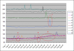
I found three unexpected characteristics during the project development. The attached data plot shows several features ('A' to 'D') that are listed below
  1. The sensitivity and response threshhold differed between inputs (refer to the 9 different traces: four are almost identical and a fifth is very similar, while the remaining four have quite different levels).
  2. Touching one pad could provide a response on another input (A, B and C).
  3. Turning outputs on and off (to drive the LEDs) changed the response threshholds of the Touch inputs (D - The software turned on an output as each pad was touched in sequence).
So the software needs to detect a change in Touch reading that is sufficiently different to the longer term average reading.

My solution ended up being quite complex - I used a timer to sequentially read the Touch inputs every 100mS and record the average of each input into a variable. These values became the reference level for each touch input pin so that a touch on each touchpad could be recognised. Fortunately, the project was a paid commission, so I got paid for my efforts!

Edit: I incorrectly specified using a 20M2. I finished the project with a 28X2.
 

Attachments

Last edited:

piclt

Member
My solution ended up being quite complex
good info, Yes I found that, but didn't document it so well, I have used setting a threshold for each "as not touched pin" by using for/next to read all the pads to a lookup then when checking which pad is touched, by comparing the touched value to the value in the lookup for that pin + a threshold. If greater then detect as touched.
Your 100 mS for a touch read is a long time......makes detection very slow.
What was you config bits settings and setfreq........ all these settings vary the actual size of the readings and speed of response. in manuals not much info on how they interact or best settings...??
 

inglewoodpete

Senior Member
Your 100 mS for a touch read is a long time......makes detection very slow.
What was you config bits settings and setfreq........ all these settings vary the actual size of the readings and speed of response. in manuals not much info on how they interact or best settings...??
100mS proved to be adequate for this application. In practice, it was difficult for the touch to be less than 100mS
I checked the code file - it was actually a 28X2 running at 8MHz, with Timer interrupts every 100mS. The client originally supplied a 20M2 but it was unsuitable due to its inability to have a 100mS timer configured - I finished the development using a 28X2.
Config bits? This is a PICAXE. (I do use config bits but that is for Programming PICs with C)
 

cpedw

Senior Member
After tinkering with Picaxe Touch for a while, I found that TTP223 was a much more reliable touch switch, and cheap and simple too.
 
Top