Parallax ColorPal sensor

tonyg

New Member
Hi, I am a Chemistry teacher learning PICAXE. My students and I are stumbling towards a soccer robot. I can issue serial commands to the Parallax ColorPal sensor and get it flashing various colours but I can't read the hex code coming back on the same line. How do I read a 3 digit hex on the serial pin? I'm using 18M2 and 28X2. This is my code:

main:
label_5: pause 1000 'Wait command
serout C.6,T2400_8,("= R s !") 'This emits Red and issues the "sample" command
input c.6
serin [10], C.6,T2400_8,varA,varB,varC 'I have no idea how to receive the 3 digit hex code back from the colorPal, I also tried #VarA etc
output c.6
debug
goto label_5

Any suggestions greatly appreciated.
 

hippy

Ex-Staff (retired)
This appears to be the product ...

http://www.parallax.com/tabid/768/ProductID/617/Default.aspx

From the datasheet ...

Communication with the ColorPAL takes place using serial I/O, transmitting and receiving at between 2400 and 7200 baud, using a non-inverted, open-drain protocol. The ColorPAL includes a pullup resistor to Vdd, so you do not need to apply one externally. Because of the open-drain protocol, the pin used to communicate with the ColorPAL should always be configured as an input, except when being driven low. Also, when starting up, you should wait for this pin to be pulled high by the ColorPAL before trying to send it any commands.
Though the current PICAXE code perhaps works it would be advisable to ensure the interface is electrically safe. The best method for that is a separate output and input pin, and diode on SEROUT pin to ensure it only pulls low to meet requirements of an open-drain style signal bus.

For receiving data in, I'd start with -

SerIn pin, baud, b1, b2, b3

Then see what format the three variables are in. I'd guess ASCII characters, "0" to "9", "A" to "F" or "a" to "f".

Then it's a matter of converting those to digit values $0 to $F, and then combing to create a 12-bit value $000 to $FFF. Untested and scope for optimisation...

Serin pin, baud, b0, b1, b2
If b0 > "9" Then : b0 = b0 + 9 : End If
If b1 > "9" Then : b1 = b1 + 9 : End If
If b2 > "9" Then : b2 = b2 + 9 : End If
b0 = b0 & $0F
b1 = b1 & $0F
b2 = b2 & $0F
w0 = b0 * $10 + b1 * $10 + b2
 
Last edited:

Technical

Technical Support
Staff member
You need to receive 3 ascii charcters into 3 bytes, so you were almost right. Each byte will then contain the ascii character "0-9" or "A-F"
You don't need the input/output commands as these happen by default within serout/serin. You can safely use one pin as the sensor has a safety 330 resistor on the data line.

Do this to start with - do the b0,b1,b2 values change?

Code:
main:
pause 1000    'Wait command
serout C.6,T2400_8,("= R s !")  'This emits Red and issues the "sample" command
serin [10], C.6,T2400_8,b0,b1,b2   'I have no idea how to receive the 3 digit hex code back from the colorPal, I also tried #VarA etc
debug
goto main
If so someone like Hippy will then write you a fancy 'hexascii' to binary conversion routine!

Edit > See, he did so whilst we were still typing!
 

westaust55

Moderator
From the manual:
Because of the open-drain protocol, the pin used to communicate with the ColorPAL should always be configured as an input, except when being driven low.
Also, when starting up, you should wait for this pin to be pulled high by the ColorPAL before trying to send it any commands.
accordingly, the code may need to be more akin to this:
Code:
SYMBOL varA = b0
SYMBOL varB = b1
SYMBOL varC = b2


main:
label_5: pause 1000 'Wait command
hold:
	IF pinC.6 = 0 THEN hold
	output c.6
	serout C.6,T2400_8,("= R s !") 'This emits Red and issues the "sample" command
	input c.6
	serin [10], C.6,T2400_8,varA,varB,varC 'I have no idea how to receive the 3 digit hex code back from the colorPal, I also tried #VarA etc
	debug
	goto label_5
Note it is good practice to include you relevant, if not all, SYMBOL statements so others can test your code in the PE simulator without having to add suitable assignments.
 

tonyg

New Member
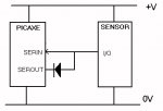
More infor on ColorPal sensor

Hi, thanks for your advice. I admit to being way out of my depth. I put in the code to wait till the pin was high before proceeding but that just hung because the colorpal does pull the signal line high but if it is attached to an input pin its goes low (don't know why), anyway I know that is not the issue because just putting a wait in the begining works just fine and I know the pin is high before I issue a serial command and also the colorpal does what is told and turns the RED LED on.

This is the code I used:

'BASIC converted from Logicator for PICAXE flowsheet:
'C:\Users\Tony\Documents\colorpal.plf
'Converted on 6/3/2012 at 11:10:54

symbol varA = b0
symbol varB = b1
symbol varC = b2


let dirsB = %11111111


main:
label_5: pause 50 'Wait command
'hold:

'If pinC.6 = 0 then hold
output C.6
serout C.6,T2400_4,("= R s !")
input C.6
serin[10], C.6,T2400_4,varA,varB,varC
debug
goto label_5


#no_data 'reduce download time


I have almost no experience interpreting the oscilloscope and no formal training in electronics. This is the trace I got on the colorpal serial pin.red command and sample command.jpg
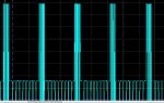
If I just tell the colorpal to turn the red on and not to send a "sample" back I got this trace. red command only.jpg 
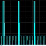
I think they are the same meaning there is no serial data coming back to the pic? I know the manual said the pin should be configured as an input except when being driven low and I know from playing around and watching the trace that as soon as I put the signal line from the colorpal onto the pic pin it sucks it low? It seems logical that the serial line being pulled low is preventing the reception of the serial data into the pic? I am clutching at straws in the dark really. If anybody wants me to psychically post them one of these things I have a box of them that I can't get to work. If another teacher wants the dozen colorpals I have you can have them for free (unless I can get it going with 1 more hours effort). If it is something obvious let me know otherwise I will probably need to move on to another sensor.

Thanking you for any assistance rendered.
 

hippy

Ex-Staff (retired)
I think they are the same meaning there is no serial data coming back to the pic?
It is possible the transmission circuit in the sensor has burned out. An open-collector or open-drain bus is only pulled low by the transmitter; if the PICAXE output is high when the bus is pulled low the supply is shorted, +V through the PICAXE to to bus, bus to 0V through the sensor.

To avoid that the PICAXE and sensor should be wired as attached.
 

Attachments

westaust55

Moderator
If anybody wants me to psychically post them one of these things I have a box of them that I can't get to work. If it is something obvious let me know otherwise I will probably need to move on to another sensor.

Thanking you for any assistance rendered.
Are you located at Rainbow Beach in Queensland? If Queensland, you could try mailing one sensor to myself and I will see if I can get one working for you.

Have you tried all of the 12 sensors you have or are there some you have not yet tried. Best option would be an untried one but otherwise any one would suffice to see what I can read from it.

It can take up to 5 days for mail from Qld to reach Perth, WA. As such such an option will not be a quick solution.
Send me a PM if you are interested.
 
Top