Output from 12V alternator to PicAxe ADC pin for a rev-counter can anyone help?
- Thread starter kando
- Start date
Pongo
Senior Member
If this is the engine's original alternator that's charging the battery then there is no voltage available that will be proportional to RPM. You may be able to measure the frequency of the AC at the Field terminal and that will be proportional to RPM (well, ignoring belt slippage).
Thank you very much for replying so soon. I don't know a lot about alternators, they charge batteries!
the vehicle I have in mind is an old digger. Mini excavator. I think it is a standard run of the mill car alternator. I believe it has three pins and one of them can be used for connection. Not sure which one. It's a Volvo EC35. It probably has a high- pressure fuel line but I'm unsure of that. Sorry I can't be more helpful at the moment. If you tell me what you need to know I will try and find out.
thanks for the support for my little project.
Ken.
An alternator usually give a rectified 3-phase output. Can you measure AC or part of an AC signal at the main terminals? Use your oscilloscope to measure and tell us what amplitudes you are getting. If you can see it on your 'scope then, with a little jiggery-pokery, you can get it into your PICAXE.
Also, send us a picture of the terminals on your alternator - a nice clear one please and not an old blurry thing.
I take it you haven't done any Internetty research of your own? e.g. Google alternator measure rpm.
Also, send us a picture of the terminals on your alternator - a nice clear one please and not an old blurry thing.
I take it you haven't done any Internetty research of your own? e.g. Google alternator measure rpm.
I have found some info on the alternator:
model:A7T02071 regulator type:IC Rated power: 12V-50A
I hope this helps. It doesn't have to be that accurate. Measuring the frequency of the AC at the Field terminal seems hopeful. Does that mean I would have to stick it through a frequency to analogue chip? I have an lm2917n-8 chip in a box. But how would you attach the alternator end?
Ken
a quick google search on the part reveals:
12V 50A ALTERNATOR MITSUBISHI S4L SL SQ SS INDUSTRIAL ENGINES A7T02071
looks like the one.
Last edited:
Jeremy Harris
Senior Member
The alternator output won't be true DC, but three phase rectified AC, which has probably got enough ripple on it to be able to AC couple it to a comparator. The resulting square wave can then be fed to a Picaxe pin and the Picaxe used to measure the frequency of the pulse train.
It might take a bit of fiddling about to get it to work, but once you've got a pulse train from the comparator then the rest should be pretty straightforward.
It might take a bit of fiddling about to get it to work, but once you've got a pulse train from the comparator then the rest should be pretty straightforward.
premelec
Senior Member
You could take an "ordinary" lines transformer with split primary to use for isolation of the alternator signal - in this application the transformer would be used 1:1 ratio and at different frequencies than 50 Hz. Anyhow connecting one - 120 v winding - across the alternator output through a capacitor and using the other 120 volt winding to output an isolated AC signal of the frequency of the alternator - A capacitor in series with the winding going to the alternator limits any DC current in the alternator winding - or resistor in series with the winding could work. The type of transformer I'm referring to is one that would be used for 120v OR 240v AC input - not too important what the output secondary voltage is.
neiltechspec
Senior Member
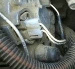
Looks to me like that alternator has a "W" connection, the single small spade connector that is recessed.
That is the AC output used for driving tachos on diesels. Lots of older diesel cars / vans used that connection. Newer ones (common rail injection) use a signal from the ECU.
No idea how you would use it though.
That is the AC output used for driving tachos on diesels. Lots of older diesel cars / vans used that connection. Newer ones (common rail injection) use a signal from the ECU.
No idea how you would use it though.
But the ripple can be negligible when the attached battery is fully charged, I would think some clever pre-processing/AGC would be required to extract a reliable signal from just a few mV, while rejecting noise from other sources. (Lead-acid battery = very large low impedance capacitor!)The alternator output won't be true DC, but three phase rectified AC, which has probably got enough ripple on it to be able to AC couple it to a comparator.
There are indeed automotive alternators with an RPM output - usually tapped from an alternator phase before rectifiers. This one is a "one wire" type, meaning the rectifier & regulator are integral, and there's no direct access to field or rotor windings unless specially provided ; I do not think there is any such provision on this model.
If you're confident enough, you could open it up and modify by attaching a wire to one phase for your RPM pickup.
You wouldn't use picaxe ADC for this usually, you'd use pulsin or count to determine RPM.
The electronic part is easy to get the signal to the picaxe and only requires a opto coupler to isolate the AC, but where the real problem is with most auto alternators is the field windings are switched on and off by the voltage regulator, to maintain a regulated DC output.
This will mess with your pulse count something shocking, and all you will get is garbage for your RPM reading.
I think some diesel alternators might include a small permanent magnet to induce a weak AC voltage into the windings or include a separate winding for the taco.
How i have setup tacos on diesel motors (excavators, bobcats, tractors etc, ) is to use a proximity sensor and detect a passing nut or bolt on a rotating pulley or shaft somewhere on the machine, dead simple and you know exactly what you have to work with.
First of all. Thank you very much for all the support so far. It’s always appreciated and good to know that there is always someone out there willing to help others.
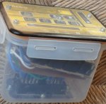
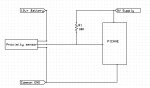
The reason behind this little project is that some time ago the control box on the digger crashed out and refused to work. After finding out the price of a new one I decided to have a go and make my own. I succeeded using a plastic box some relays and transistors . (see picture). It got the digger working with the safety bits installed but three things did not work. This is one of them. After all what is a digger other than just an oversized robot toy! Great fun though.
Jeremy. Yes I think it is a 3 phase rectified AC. Aren’t they all? I have seen something about using a lm339 comparator chip to do what you say. It looks complicated and perhaps above my capability. I will give this some thought and look it back up on the internet.
Premelec. I don’t know what a lines transformer is and your method looks even more daunting. I expect though if it were explained I might get the gist of it.
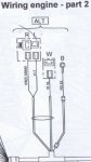
Neiltechspec. That is what I had in mind. I am sure that the third small wire is for the tacho see the photo and diagram attached. I was hoping that someone could give me a way of connecting this to the picAxe pin. Is it not done simply with a series resistor and zenor diode of say 4.7v? I don’t know. Can any one help on this part? And which Picaxe pin an ADC or normal input?
Rossko57. I read something on the net about taking the little ripple left after rectification.. amplifying it and using that to do the RPM. Above me I think but good to state on the forum as someone else may have an idea with this solution.
SAborn. To “use a proximity sensor and detect a passing nut or bolt on a rotating pulley or shaft somewhere on the machine, dead simple and you know exactly what you have to work with”. Is perfect but I want to try from the original connection. If it was there before my control box crashed it must be still there now. Having said that if nothing else comes I would like to count on your expertise on the way you do it.
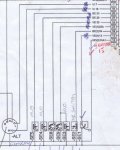
So gentlemen thank you very much for your input but I still feel thwarted. Here is a bit diagram of wiring loom from ALT alternator of the digger and a photo (best I could get in the cramped space) of the rear of the alternator. There is a separate wire which I think is the tacho pin or “W” connection.
So I am still looking for help please.
The reason behind this little project is that some time ago the control box on the digger crashed out and refused to work. After finding out the price of a new one I decided to have a go and make my own. I succeeded using a plastic box some relays and transistors . (see picture). It got the digger working with the safety bits installed but three things did not work. This is one of them. After all what is a digger other than just an oversized robot toy! Great fun though.
Jeremy. Yes I think it is a 3 phase rectified AC. Aren’t they all? I have seen something about using a lm339 comparator chip to do what you say. It looks complicated and perhaps above my capability. I will give this some thought and look it back up on the internet.
Premelec. I don’t know what a lines transformer is and your method looks even more daunting. I expect though if it were explained I might get the gist of it.
Neiltechspec. That is what I had in mind. I am sure that the third small wire is for the tacho see the photo and diagram attached. I was hoping that someone could give me a way of connecting this to the picAxe pin. Is it not done simply with a series resistor and zenor diode of say 4.7v? I don’t know. Can any one help on this part? And which Picaxe pin an ADC or normal input?
Rossko57. I read something on the net about taking the little ripple left after rectification.. amplifying it and using that to do the RPM. Above me I think but good to state on the forum as someone else may have an idea with this solution.
SAborn. To “use a proximity sensor and detect a passing nut or bolt on a rotating pulley or shaft somewhere on the machine, dead simple and you know exactly what you have to work with”. Is perfect but I want to try from the original connection. If it was there before my control box crashed it must be still there now. Having said that if nothing else comes I would like to count on your expertise on the way you do it.
So gentlemen thank you very much for your input but I still feel thwarted. Here is a bit diagram of wiring loom from ALT alternator of the digger and a photo (best I could get in the cramped space) of the rear of the alternator. There is a separate wire which I think is the tacho pin or “W” connection.
So I am still looking for help please.
Jeremy Harris
Senior Member
Nope, the rotor is PWM'd to control the output, by varying the magnetic field in the rotor, there is no switching at the high current field windings at all. The field windings just go directly to six diodes, normally, with no switching or smoothing. As already mentioned, some diesel alternators have an additional single phase tacho winding, which can be used, but this one doesn't seem to have that.The electronic part is easy to get the signal to the picaxe and only requires a opto coupler to isolate the AC, but where the real problem is with most auto alternators is the field windings are switched on and off by the voltage regulator, to maintain a regulated DC output.
This will mess with your pulse count something shocking, and all you will get is garbage for your RPM reading.
I think some diesel alternators might include a small permanent magnet to induce a weak AC voltage into the windings or include a separate winding for the taco.
How i have setup tacos on diesel motors (excavators, bobcats, tractors etc, ) is to use a proximity sensor and detect a passing nut or bolt on a rotating pulley or shaft somewhere on the machine, dead simple and you know exactly what you have to work with.
My experience has been that there is always loads of ripple directly at the alternator terminal, as the impedance of the lead from the alternator to the battery is usually high enough to ensure at least half a volt or so of ripple, which is plenty to clean up with an AC coupled comparator.
Jeremy,
Yes i basically agree, but from every alt. voltage reg i have ever checked out there is no fancy PWM, its a simple circuit of........ above 14.2 +/- volts = alternator OFF ( no excitation to the field windings) below 13.8+/- volts alternator ON (field windings excited) and thats it, although this will give a form of PWM, when you consider engine rpm and current load etc, but the ripple could cause false readings, but i also susspect the regulator PWM is far higher than the 3 phase frequency so it might not be a problem.
I have built many tacos for permanent magnet alternators which is a given as the field is alway there as long as there is rotation, and even they can have false ripple due to increasing/decreasing rpm across the coils.
Its the once in a blue moon spike that throws the entire system out of whack.
I also agree there is enough ripple on the alternator output to extract a reading from, all you need do is place a AC current tong meter on the alt, cable to the battery and you will read the current in the cable. (proof of AC ripple)
Saborn. Sorry but there are no markings at all.
But checking the wiring diagram attached above The R and L is the double white connector the battery connection is the B and the big black bulbous wire on the photo which leaves the W connector by itself and the wire itself has VI 16 physically printed on it so I assume with 99% certainty that this is the W. The other end of VI 16 ends up at the control box pin in the cab. You can just about make out OR205 on one of the white wires on photo which corresponds to the R on the wire diagram.
Ken
But see part wire diagram of this which might help. the other end of the wire W from ALT goes into what used to be the original ECU which crashed on me.
Last edited:
Jeremy Harris
Senior Member
But the field windings aren't normally switched at all, the three windings on the field stator are hard wired directly to the six rectifier diodes. The single armature (rotor) winding is switched, and you're right, the PWM is crude, just an on-off whenever the voltage threshold is passed. The current through the armature is modest, though, usually just a few amps at most, which is why switching it to regulate voltage is a lot simpler than trying to switch the high current field windings.Jeremy,
Yes i basically agree, but from every alt. voltage reg i have ever checked out there is no fancy PWM, its a simple circuit of........ above 14.2 +/- volts = alternator OFF ( no excitation to the field windings) below 13.8+/- volts alternator ON (field windings excited) and thats it, although this will give a form of PWM, when you consider engine rpm and current load etc, but the ripple could cause false readings, but i also susspect the regulator PWM is far higher than the 3 phase frequency so it might not be a problem.
I have built many tacos for permanent magnet alternators which is a given as the field is alway there as long as there is rotation, and even they can have false ripple due to increasing/decreasing rpm across the coils.
Its the once in a blue moon spike that throws the entire system out of whack.
I also agree there is enough ripple on the alternator output to extract a reading from, all you need do is place a AC current tong meter on the alt, cable to the battery and you will read the current in the cable. (proof of AC ripple)
The diagram shows Alternator with FOUR wires plus an earth; looks like B R L and WBut see part wire diagram of this which might help.
You may find these identifiers on the alternator casting
I think you'll find this helpful
http://www.pjldiesel.com.au/docs/91.pdf
For Mitsubishi alternators, L is for the warning Lamp and W is a phase tap (for RPM) which is the one you're after.
EDIT: wotcha gonna do with RPM when you have it, drive a bargraph kind of thing? Calibration may be fun, as although you could work out alternator RPM from measurements, that isn't the same as engine RPM. Less problem if you're looking for a fairly coarse display.
Last edited:
@Kando,
Now that you have some decent info on what may or may not be possible, how do you propose to do any testing / signal confirmation without an oscilloscope? With this kind of project you need a scope unless you are happy with guessing, blowing up chips & working in the dark.
But, You might get lucky and someone will do the design work & code for you, but then what will you have learned ?
Rossko57. Thank you very much for the information and that you believe the W one is the right one to connect to.
My original question still stands; nearly….
I was wondering how I could attach one of the outputs from a 12v alternator for a diesel engine to an ADC pin on a Picaxe chip so that I can create a rev counter. Anyone any ideas?
It may not be the ADC pin on the picaxe. It also looks like it is the W connection.
Can it be done with a resistor and a zenor diode of say 4.7V?
Yes rossko57 I blew a lot of components and a lot of solderering to get my ECU in a plastic box working, so I have no problem about trying things. We learn best by trial and error. (and a little help from our friends).
How do I connect the W connection from the alternator to the pin of a Picaxe?(without use of a oscilliscope). (Sounds like how can I get the square filter to fit the round hole. In Apollo 13 good film!).
Goeytex. Yes I would like to learn along the way. As I expect a lot of others will do to. The question is now, will someone step forward to help?
Again thank you very much for the support.
Ken/Kando
I would use a 10kohm resistor and a 0.1uF across the Zener to form a lowpass filter to help filter out interfering signals. Then connect a 1kohm resistor from Zener to PICAXE input to act as a current limiter for any spikes that may drive the Zener above 4.7 volt.. . . . . Can it be done with a resistor and a zenor diode of say 4.7V? . . . .
Been there, zapped that.
Many diesel and marine alternators have a tach tap. However we now have cheap hall sensors and I'd go that way to get engine RPM.
The alternator does not run at engine RPM so you have to do more math to arrive at the engine speed. The only advantage I see to using the alternator is detection of a broken belt. Of course if you want to detect alternator belt slippage comparing the engine vs alternator RPM would be a good way to do that.
The alternator does not run at engine RPM so you have to do more math to arrive at the engine speed. The only advantage I see to using the alternator is detection of a broken belt. Of course if you want to detect alternator belt slippage comparing the engine vs alternator RPM would be a good way to do that.
Kando,
I fully understand the view of using the alternator as a rpm source as it was before, but without some knowledge of what the signal is from the alternator or equipment to view the signal, its a grey area, although i think still a doable project.
As a option for you to also consider in the background, i will give you the basics of using a proximity sensor
The reason i went to a proximity sensor was its so simple and can be fitted to any system as long as you have a bracket to mount the sensor on (a piece of metal with a hole in it) and a rotating target or several targets (bolt heads or whatever)
The proximity sensor needs a air gap of about 6mm (1/4 inch) from the target (bolt head) and as the target passes the Proximity sensor the sensor is activated.
If a NpN sensor is used, then to output is a open collector and all that is required is a pullup resistor on the picaxe input, as the proximity sensor will take the input low when a target is present, this solves differences in voltages as Gnd is common to both circuits.
A proximity sensor is normally rated from 10- 20+ odd volts and can be powered direct from the equipment battery, so very easy there.
The last proximity sensors i purchased out of China for about AU$5.00 each has been faultless. (10 of)
Please understand im not suggesting you not use the alternator, its just a alternative for you to think about if the alternator method becomes too hard.
Here is a basic schematic of how you would wire a proximity sensor with a picaxe to read rpm............ very complicated.......... NOT!
Here is a link to a proximity sensor on Fleabay, so you can see what they look like (the first one i found)
http://www.ebay.com.au/itm/1pcs-Proximity-Switch-Sensor-4mm-detection-NPN-12-Diame-/360605668842?pt=LH_DefaultDomain_0&hash=item53f5c5d5ea#ht_2630wt_932
Rossko57. Sorry I forgot to mention the four wires on the diagram listed as B,R,L and W were relating to Battery, Ignition, Lamp/charging, and as we know now “W” was the RPM connection and as I have said there are no markings on the alternator.
MikeAusp. Thank you for this information. I wasn’t sure that I could do it this way so I’m grateful for the confirmation. Would it be better to use a lower voltage zenor? Do you think I could use a frequency to voltage converter chip to the ADC pin on the Picaxe, how would that fit?
Lewisg. I know nothing about Hall sensors (best I look this up) and I just wanted to use what was already there on the digger and bring it to a control unit in the cab. As it has a wire W then I wanted to try this method. Thank you for your suggestion and I will do some research on it.
SAborn. Thank you very much for your suggestion. It looks quite easy to do and understand. I will be trying both the zenor method and this proximity method and if someone comes up with what I have to attach to the alternator for a Frequency to Voltage chip method I will try that as well.
What I intended to do when I knew how to connect the W was to start again with my Home made ECU and use something like a Picaxe 40 to complete it. I’m better at the programming side than the electronics side of things as you may have gathered. I think the Picaxe system is brilliant it lends itself to make things from small robots to huge ideas and quickly. So when I get enough information on another problem. Namely the fuel sender which I believe is using a “current mirror” I can create!
Thanks to all.
Kando/ken")
MikeAusp. Thank you for this information. I wasn’t sure that I could do it this way so I’m grateful for the confirmation. Would it be better to use a lower voltage zenor? Do you think I could use a frequency to voltage converter chip to the ADC pin on the Picaxe, how would that fit?
Lewisg. I know nothing about Hall sensors (best I look this up) and I just wanted to use what was already there on the digger and bring it to a control unit in the cab. As it has a wire W then I wanted to try this method. Thank you for your suggestion and I will do some research on it.
SAborn. Thank you very much for your suggestion. It looks quite easy to do and understand. I will be trying both the zenor method and this proximity method and if someone comes up with what I have to attach to the alternator for a Frequency to Voltage chip method I will try that as well.
What I intended to do when I knew how to connect the W was to start again with my Home made ECU and use something like a Picaxe 40 to complete it. I’m better at the programming side than the electronics side of things as you may have gathered. I think the Picaxe system is brilliant it lends itself to make things from small robots to huge ideas and quickly. So when I get enough information on another problem. Namely the fuel sender which I believe is using a “current mirror” I can create!
Thanks to all.
Kando/ken
Kando/ken, you really must check what the signal level is at that "W" pin if that's what it really is.
If the "W" output is simply a rectified 3-phase then, in addition to a low-pass filter, you will need a potential(voltage) divider.
Otherwise you will pop your PICAXE.
Does the "W" voltage amplitude vary as well as frequency (wrt RPM)? I dunno. Do you?
If it does then this means you will have to introduce some kind of compensation in code if using the analogue method.
In any event, without care, this method will give a varying value of RPM.
You may have to add more smoothing or averaged ADC sampling.
I'd be tempted to look into a comparator/threshold method to turn the AC into a pulse-train.
After that you can count the pulses digitally.
But, all these things need double-checking with a 'scope. You may strike lucky without one....
And , remember, a ZenEr doesn't just have a sharp cut-off. As you approach the zener voltage it will start conducting.
Therefore, as your sample voltage approaches the zener voltage it will start affecting your ADC value.
Most ADCers use a clamp diode pointing up to the PICAXE Vsupply (input resistor/current limited).
You don't need frequency-to-voltage chip _if_ you are using the Picaxe to process.
Make up the zener-based input limiter, and attach to W. Write a Picaxe test program to monitor what you get for PULSIN out of that. I'd be expecting pulses in the 2-20mS league. You'll want to check at idle and increasing RPM to see what values you get. You'll want to check that it remains consistent with heavy electrical loads applied (that could alter the W output) at any given actual RPM.
I don't think a scope or heavy maths will be required if you can monitor from a Picaxe test program while running the machine - you're not really interested in the actual RPM to drive a bargraph, only rough percentages of the idle-to-max range.
We/you are assuming that the original circuit only used RPM for display - no fancy RPM limiting system or whatever.
It makes a lot of sense to use the original fittings, and not have to add extra sensors and wiring in the engine bay, horrible environment.
I do wonder what the purpose is of an RPM indicator on this kind of machine though !
Dippy,
Thanks for the information I will take this on board. I think I might have to ask around for the loan of an oscilloscope. or in this case I might just leave the RPM bit out of the equation all together and just do the rest of it. I do like the sound of the proximity sensor though.
Kando
Thanks for the information I will take this on board. I think I might have to ask around for the loan of an oscilloscope. or in this case I might just leave the RPM bit out of the equation all together and just do the rest of it. I do like the sound of the proximity sensor though.
Kando
Jeremy Harris
Senior Member
The proximity sensor idea is a good one, easy to implement and pretty foolproof. I fitted a similar system to an engine years ago. I bought some cheap 3mm diameter neodymium magnets from Ebay, drilled a 3mm hole near the edge of a convenient pulley on the engine and glued the magnet into the hole. I then used a cheap Hall effect sensor mounted on bracket to detect the magnet passing it. This gave a nice clean pulse once every revolution of the pulley. The sensor can be powered directly from the Picaxe supply and the pulse can be used to simply derive engine rpm with a Picaxe. This would be the easiest way to measure engine RPM I think, probably simpler electrically, although it would involve a little bit of mechanical fabrication.
A scope would be handy here, but if you dont mind a more basic approach, try placing a led with a 1K series resistor between the W terminal and Gnd, and see if the led will light, if it dont then try W terminal and V+, just remember to reverse the led.
The worst that will happen is you burn a led up, or it dont work at all.
If you can light a led from W terminal and not destroy the led, then you have a method to work with.
I always use an opto coupler for these applications so it isolates the alternator output from the picaxe circuit.
An opto coupler is simply a led that drives a photo transistor all within one chip, so both circuits are isolated by a light beam, and hence if you can drive a led from W terminal then you can drive a opto coupler......... first problem solved.
The opto coupler then just needs a pullup resistor on the picaxe input, as its a open collector, basically the same input circuit as for the proximity sensor.
Personally i would not mess with the zener diode method, and jump straight to using a isolated method of the opto coupler, but that just my choice.
Funny innit, meself I wouldn't mess with optocouplers - there'd be precious little isolation, you have common ground and power supplies after all. I don't see much risk of unpleasantless from a phase tap, not like a spark ignition pickup. The alternator already includes the necessaries for RPM detection without additions. But there is always more than one way to skin a cat
If you make up the LED tester, I would recommend an opposed diode parallel across the LED to protect from possible reverse polarity from the AC source, they are generally not good at handling reverse polarity voltages. Web search "LED for AC use". Same applies to optocoupler if you go that route.
If you make up the LED tester, I would recommend an opposed diode parallel across the LED to protect from possible reverse polarity from the AC source, they are generally not good at handling reverse polarity voltages. Web search "LED for AC use". Same applies to optocoupler if you go that route.
Make up the zener-based input limiter, and attach to W. Write a Picaxe test program to monitor what you get for PULSIN out of that. I'd be expecting pulses in the 2-20mS league. You'll want to check at idle and increasing RPM to see what values you get. You'll want to check that it remains consistent with heavy electrical loads applied (that could alter the W output) at any given actual RPM.
We/you are assuming that the original circuit only used RPM for display - no fancy RPM limiting system or whatever.
Rossko57. I must have missed your comments above on replying to the others. Sorry about that. Didn't mean to miss you out. I'm going to try your method next.
Will try it with 10k resistor then 4.7V zenor diode with 0.1uF across the zenor then 1k resistor to a pin of a 08M2 picaxe. Anything else I need? pull up/pull down or straight onto pin?
I suppose I'm going to have to use an OLED to get something of a result. Thank you for this. I will let you know how it goes.
SAborn. I have put a 1k resistor then LED and IN4001 and tried it to see if it lights to gnd. Yes it does. so I can probably use the opto method.
Last edited:
Did you try reversing the polarity of the led between W terminal and ground to see if it worked both ways (AC voltage) or just works the one way (DC voltage)
As you see there is several input options put forward, and any or all will likely work.
I tend to work on caution with this sort of application, and feel any isolation is good design practice, i have built a few to learn the pit falls of a simple circuit to extract a pulse from a alternator AC.
You may well get odd little spikes that cause high abnormal readings with either AD/DC signal method, thats without sufficient filtering or wave shaping between the input circuit and picaxe, in your case perhaps a high flicker of RPM on a display will mean little to your needs, or not even effect you.
In a system where things are controlled by the RPM reading, noise spikes on the alternator input can cause all sorts of problems to equipment.
Filtering is a issue you might need to consider later, once you have a rpm signal to work with.
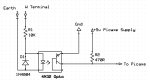
Here is a Opto coupler input circuit, that has been used to extract a signal from many alternator RPM circuits in use. (no filtering included)
You might need to reduce R1 depending on the voltage on W terminal.
With using Pulsin you should beable to read a count value from the circuit, then you have a data signal to work with.
As you see there is several input options put forward, and any or all will likely work.
I tend to work on caution with this sort of application, and feel any isolation is good design practice, i have built a few to learn the pit falls of a simple circuit to extract a pulse from a alternator AC.
You may well get odd little spikes that cause high abnormal readings with either AD/DC signal method, thats without sufficient filtering or wave shaping between the input circuit and picaxe, in your case perhaps a high flicker of RPM on a display will mean little to your needs, or not even effect you.
In a system where things are controlled by the RPM reading, noise spikes on the alternator input can cause all sorts of problems to equipment.
Filtering is a issue you might need to consider later, once you have a rpm signal to work with.
Here is a Opto coupler input circuit, that has been used to extract a signal from many alternator RPM circuits in use. (no filtering included)
You might need to reduce R1 depending on the voltage on W terminal.
With using Pulsin you should beable to read a count value from the circuit, then you have a data signal to work with.
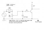
Here's another simple circuit that has been tested to work. There is no optical isolation, but personally I don't think that is necessary anyway. The 2N222 ( or equivalent) transistor greatly improves the rise & fall times of the output signal vs a sluggish Opto. Another option could be to replace the transistor with a Schmitt Inverter for even better rise / fall times.
I have this circuit connected to mains (120VAC) with no problems at all. I have also used this circuit to generate pulses from an ignition coil.
With the engine at idle, adjust the pot with the center tap disconnected from the rest of the circuit so that the center tap reads ~6VAC.
I have this circuit connected to mains (120VAC) with no problems at all. I have also used this circuit to generate pulses from an ignition coil.
With the engine at idle, adjust the pot with the center tap disconnected from the rest of the circuit so that the center tap reads ~6VAC.
Attachments
-
 26.6 KB Views: 28
Thank you guys. I'm trying both these methods. I just need some time to try them.. Digger is in the field so I have to take everything out to it then back just to adjust the program..
Neat diagrams and just what I want.
SAborn. No I didn't try the gnd way around with the LED. When connected the positive way straight from W connection it was flickering on and off at low revs I assume from that it was AC. But I will try it and let you know.
Ken.
Neat diagrams and just what I want.
SAborn. No I didn't try the gnd way around with the LED. When connected the positive way straight from W connection it was flickering on and off at low revs I assume from that it was AC. But I will try it and let you know.
Ken.