Output 0 problems

james1

New Member
I have a problem with a multi colored LED.
I am using this LED which is 3 colored, 4 leged. This LED has a common anode so I have to use the low command not high. While the 08M was on the schl. ex. board pin 0 was not very bright. Even with the other LED legs on pin 0 it is always dim. I then took the chip off thew board and had just the LED soldered on. Now LED on pin 0 doesn't go at all. (again, it is not the LED) The multimeter says the pin is going and a normal LED works fine. The LED is round the right way and the batteries are fine. A tie down resistor on SerIn doesn't seem to help.

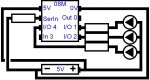
Here is my shematic...

Code:
   +------------------+          multicolor LED
   |     .----------. |               ____
   |     |PICAXE 08M| |              /    \
   | +-o-|5V      0V|-o        +--o---|<-o |
   | |  -|SerIn Out0|-o--------+    |    | |  common
   | |  -|In4   Out1|-o-----------o---|<-o---o anode
   | |  -|In3   Out2|-o--------+    |    | | |
   | |   '----------'          +--o---|<-o | |
   | +--------------------+          \----/  |
   |                      |                  |
   |              |  |  | |                  |
   +-----------o-||-||-||-o------------------+
               -  |  |  | +
5VAnd a basic version of my code...

Code:
output 0
output 1
output 2
symbol time = w1     'w1 is used as pause time

main:
let w1 = 1000     '1 sec

flash1:
let pins = %0000011     'as the led is backwards the pin neads no be negative
pause time     'pause for w1 value
let pins = %0000101     'pin 1
pause time
let pins = %0000110     'pin 0
pause time
if time = 0 then goto flash2   'if there is no delay between flashes go to flash2 sequence
let time = time - 50     'time value is decreased by 50
goto flash1     'loop back with new pause time

flash2:
let pins = %0000011     'as the led is backwards the pin neads no be negative
pause time     'pause for w1 value
let pins = %0000101     pin 1
pause time
let pins = %0000110     pin 0
pause time
if time = 1000 then goto flash1   'if there is a 1 sec delay between flashes go to flash1 sequence
let time = time + 50     'time value is increased by 50
goto flash2     'loop back with new pause time
Any ideas
 
Last edited:

BCJKiwi

Senior Member
I've just had a quick look at this so please excuse me if I have the wrong end of the stick!

As you have a common anode, the supply positive voltage is applied to the anode so the three individual led pins are relatively negative and the current therefore has to flow INTO the PICAXE Ports. Therefore you need to be using inputs (or ports you can turn into inputs). You don't appear to be doing that.

High / Low will turn the port On /Off but not change it from an output to an input.
By the way, Output 0 can ONLY be an output.

ENSURE you put current limiting resistors in each input! The inputs will only handle 20mA each MAX! Check your LED specs for current and use the calculator at
http://led.linear1.org/1led.wiz
to work out the minimum size of resistors you need.

Suggest you try two of the LEDs on legs 3 (in 4) and 4 (In 3) which are inputs by default. This will test the suggestion I've made and if correct will give you the lead on how to sort the problem.
 
Last edited:

SD2100

New Member
Also your program is setting TIME to 1000 then counting down in steps of 50, when 0 is reached it jumps to flash2. Now that TIME is 0 there is no pause to slow it down so the flashing will be too fast to see.
When it gets to "if time = 0 then goto flash1" it is sent back to flash1 and never gets to "let time = time + 50" to increase the delay time. From then on it just races between flash1 and flash2 because TIME is always set to 0.
 

james1

New Member
Hi Phil,
The code was meant to say 1000. I copied the first section but forgot to change that bit. I have now edited it.

That sounds like a good idea BCJ, I will try it and let you know.
 

BCJKiwi

Senior Member
Your flash1 and flash2 routines are also the same so you won't be able to tell which is which. suggest you change one.

You can solve issues like this by using the simulator:-

Click on;
Simulate
Step
and then on the '}' button repeatedly.

This will step through the program and you can see if it follows the logic you expected and if not, where it fails. It will also show the value of the variables along the way. You can also double-click on a variable to change its value so if your program is in a repeating loop which is working, you can reset the variable close to the end of the loop to check the next part of the program.

Give it a try!

I think you may have missed Phil's point;

this code:-

if time = 0 then goto flash1 'if there is a 1 sec delay between flashes go to flash1 sequence
let time = time + 50 'time value is increased by 50
goto flash2 'loop back with new pause time

never reaches;

let time = time + 50 'time value is increased by 50

as it "goes to" flash1 before that line so the time never resets from 0.

you need something like (untested)

if time = 0 then 'if there is a 1 sec delay between flashes go to flash1 sequence
let time = time + 50 'time value is increased by 50
goto flash1
else
goto flash2 'loop back with new pause time
endif

But this doesn't make much sense but will give you the logic. As I don't know waht you are trying to achieve I'm not sure what else to suggest.
 
Last edited:

james1

New Member
BCJ, my actual code works just as I want and I understand it.

What this does is flash the 3 LEDs one after another with a 1 sec interval. Then decreases the pause time so the flashes will be faster. Eventually the pause is 0 a which piont the sequence changes. The time then increases and slows down the flashes. And loops forever (until turned off).
 

kevrus

New Member
I believe that when you make an output high, you are sourcing current (up to the 20mA max) which would effectively measure 5v with respect to -ve hence the pin becomes positive.
When you make an output low, you are sinking current (again up to the 20mA max) which would measure 5v with respect to +ve making the pin negative.
To operate each colour of your common anode LED, you would need to make the relevant output low, but a current limiting resistor is essential to prevent damage. This is best done with a resistor for each colour as the different colours usually have different forward voltage drops, and would eliminate problems when two or more colours are lit simultaneously.
Picaxe manual 3 shows output pin/LED configurations.
 

Tom2000

Senior Member
If you purchased your LEDs from a Chinese vendor on eBay, check the pinouts with an ohmmeter.

I bought some of these, and the pinouts didn't match those shown in the auction description.

Have fun!

Tom
 

BCJKiwi

Senior Member
@ kevrus
The manual clearly states that High and Low turn an output on or off and where the pin is configurable, it makes it an output - i.e. it cannot sink current as an output.

@ darthtader
Your code will do what you have described - I just did not understand that was what you were trying to achieve - I had just picked up on Phil's comment.

When you say pin 1, do you mean Leg 6 - In1/Out1/ADC1? If so then you are actually on a Port that is input by default so it should work OK - the same for pin2.
Pin0 is however an output and can only be an output so would either not work at all or be very dim as you describe.

If this is still what you are getting, suggest you move the connections along 1 to Pin1, 2 & 3.
 

hippy

Ex-Staff (retired)
A tie-down resistor on Download Serial In to 0V is essential, and so are current limiting resistors for LED's; either one for each cathode ( pointy-end ) between O1, O2 and O3 and the LED's or one between the common anode and +V.

As testing shows O0 works and can drive a normal LED it may be that you've damaged your RGB LED.

Try swapping the different colour LED's with different output pins to see if you can determine exactly what does and doesn't work. Also, don't try using a complicated program like you already have. Use a simple program to get the hardware working first, then bring in the complexity ...

Code:
High 0 : High 1 : High 2
Do
  Toggle 0 : Pause 1000 : Toggle 0
  Toggle 1 : Pause 1000 : Toggle 1
  Toggle 2 : Pause 1000 : Toggle 2
Loop
 

hippy

Ex-Staff (retired)
The manual clearly states that High and Low turn an output on or off and where the pin is configurable, it makes it an output - i.e. it cannot sink current as an output.
You're right that an output is either 5V (high) or 0V (low) but sourcing and sinking current depends on what the output connects through and to. It's about voltage differences.

If the output is connected via an R to a 2V5 point, when the output is high (5V) current will flow from the output to the 2V5 ( sourcing ), when output is low (0V) current will flow from from the 2V5 into the output ( sinking ).

By adding a blocking diode in the output line, the output pin can be 'no current or sourcing current' or 'no current or sinking current'. LED's with common anodes create the latter configuration.
 

kevrus

New Member
Please correct me if i'm wrong, (as I usually am...) but manual 3 page 8 shows the relationship between output high and output low and the ability to sink or source current with relation to LEDs connected in inverse parallel...
 

hippy

Ex-Staff (retired)
@ kevrus : You're right. With the anode of the LED towards 5V, current will only flow when the output is low. With the cathode towards 0V, current will only flow when the output is high.

Lighting LED's is all about current flow and that current flows ( unless blocked by a diode pointing against the current ) from a higher voltage to a lower voltage. The dual-colour LED method just lower down on the page uses that fact, effectively tipping the LED's upside down when looked at from a current flow perspective.
 

BCJKiwi

Senior Member
@Hippy,
Thanks for that info. This was not apparent (to me anyway) from any of the documentation I've read to date.

One wonders then at the terminology of Input and Output as it would appear the ports are bidirectional (with respect to current) and high or low (with respect to voltage), or have I still not got the message?
 

hippy

Ex-Staff (retired)
The I/O's are effectively relay controlled switches ( between pin and +V and pin and 0V ) with resistors across them ( someone may provide a more technically accurate description ), so as outputs one or the other is closed and for input both are open.
 

BeanieBots

Moderator
No, you've missed it!
An input is a pin which is used to supply the device with a signal to read.
An output is a pin which sink or source current to another device.
Bidirectional has different meanings depending on the context.
With reference to I/O pins, it means one which can be either input or output.
An output which can only sink current is often called "open collector".
One which can only source is often called "open emmitter".

Pins such as those used by I2C comms are bi-directional AND open collector.
That way, it is possible for them to 'read' the logic level of the line, AND control the line but only by sinking current. Thus, if two try to take control of the same line, there is no smoke because they can only pull it down. The pull-up resistor is the only thing that can source current.
 

lbenson

Senior Member
BB--thanks for the explanation; it makes clear a number of issues for me: "open collector" and the specific rationale behind the pull-up resistor on I2C. Is the same technique (pull-up on an open-collector pair) used for 1-wire?
 

BeanieBots

Moderator
Yes.
Also, diode OR'ing is the same principle. Allows multiple OUTPUTS to control a single input. This was described by Hippy earlier on.
 

james1

New Member
Hi guys,

I am now using pins 1, 2, and 4.
Attached is my new schematic and below my current code.
It is complex but it works fine.

Code:
output 4
output 1
output 2
symbol time = w1

main:
let time = 1000

flasher:
let pins = %0000110
pause time
let pins = %0000010
pause time
let pins = %0010010
pause time
let pins = %0010000
pause time
let pins = %0010100
pause time
let pins = %0000100
pause time
if time = 0 then goto flasher2 
let time = time - 50
goto flasher

flasher2:
let pins = %0000110
pause time
let pins = %0000010
pause time
let pins = %0010010
pause time
let pins = %0010000
pause time
let pins = %0010100
pause time
let pins = %0000100
pause time
if time = 20 then goto flasher3
let time = time + 1
goto flasher2

flasher3:
let pins = %0000110
pause time
let pins = %0000010
pause time
let pins = %0010010
pause time
let pins = %0010000
pause time
let pins = %0010100
pause time
let pins = %0000100
pause time
if time > 1000 then goto main
let time = time + 50
goto flasher3
 

Attachments

Last edited:

james1

New Member
My code almost worked fine.:(

For some reason the pause time was very high after a couple of full loops.
I have now fixed this so the pause time is reset back to 1000 when starting again.
I might post some photos so you can see it whe nit is finished.
 
Last edited:
Top