[OT] Help with a little logic

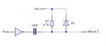
I am strugling to work out a suitable method of creating a certain logic signal to reset an IC when a USB plug is inserted.

The first graph shows the +5V supply from the USB, and the second graph shows the signal that I want to generate in accordance to the first graph.

I hope that it makes some sense, and someone is able to offer me advice because I have looked everywhere that I can think of to try and come up with a solution.

Thanks.
 

Attachments

Last edited:

Jeremy Leach

Senior Member
Well, the second graph has a negative pulse when the first graph transitions from low to high. So you just have to have code to create this. Not sure what timeline your talking about.

I'd continually read the incoming signal and have two variables call LastState and ThisState. Comparing these you will be able to determine the Low to High transition, and when you do make the output pulse low with Pulsout command.
 
Last edited:

moxhamj

New Member
Two possible solutions. 555 +/- maybe an inverter chip.

But this is a picaxe forum, so how about a pixaxe solution using an 08:
Code:
start:high 2' pin 2 is the output
main:if pin1=0 then goto main' still zero so keep testing
' got to here, so must be the beginning of a positive edge
low 2
pause 100' or whatever
high 2' back to high
waitforlow:if pin1=1 then goto waitforlow' loop while testing to see if has gone low yet
goto main ' input is now low so go back to main
 
Last edited:

ylp88

Senior Member
Again, it depends on the exact timing requirements you need, but you might even be able to get away with a common collector transistor output system with the input signal driving the transistor's base via a suitably sized capacitor.

ylp88
 

MBrej

Member
If you want to use logic, use a 555 and inverter (the 555 triggers on a low pulse). You will also need to add a capacitor, otherwise the time period will not start until the input has high again. A diode is needed to stop the capacitor generating voltages higher than the input.

Matt
 

Attachments

Thanks for the replys already, and just to clarify, I am looking at using logic gates, transistors or a 555, hence the [OT] in the title. The low period on the second graph needs only to be about 5ms, but precision does not matter.

The reason that I posted the query here is because this is the only suitable forum that I am a member of, and it is a part of a larger project that uses Picaxe.

Well for now, I will have a go with the ideas that you have already suggested, but other ideas are welcome.

Thank you.
 

hippy

Ex-Staff (retired)
I'm not quite sure where this need for a 555 comes from. A 74HC00 should do the job. Dual Schmitt NAND gates would be best. Run the Vusb through two gates to make a non-inverter into this ...

Code:
                                      ___
Vsb >----.-----.---------------------|   \
        .|.    |                     | &  )O-------> C
        | |   _|_                .---|___/
        |_|   /_\       ___      |
         |     |    .--|   \     |
      A  }-----^----{  | &  )O---' B
         |          `--|___/
       __|__+
       ==.==
        _|_

                ___________
Vusb   ________|           |_____
               :           :
               :  _________:
A      _________--          -____
               :  :
       ___________:          ____
B              :  |_________|
               :  :
       ________:  :______________
C              |__|
 
Last edited:

gbrusseau

Senior Member
Hippy,
Nice, and simple. I like it, but isn't there going to be a delay from the rising edge of USB +5 and the start of the low going C pulse. If a delay is undesireable, wouldn't a one-shot IC reduce the delay time to within about 20ns.

On the other hand, if your inserting a USB cable and sensing the +5, your going to need to debounce the sensing input signal and delay is not a factor.
 
Last edited:

moxhamj

New Member
Re: "Thanks for the replys already, and just to clarify, I am looking at using logic gates, transistors or a 555, hence the [OT] in the title. The low period on the second graph needs only to be about 5ms, but precision does not matter."

Have a read of this http://www.doctronics.co.uk/555.htm#monostable

Scroll down near the bottom for an explanation of the trigger circuit (similar to hippy's concept). You do need to get the timing right for those sorts of triggers. There is a transistor inverter if you want positive edge trigger. If you want to invert the output you can use another transistor. Or if you are inverting an input and and output, maybe worth getting a 74HC04.

A bit of work on the breadboard...
 

hippy

Ex-Staff (retired)
Hippy, Nice, and simple. I like it, but isn't there going to be a delay from the rising edge of USB +5 and the start of the low going C pulse.

No, because the output pulse going low is immediate at C because B=1 it's the lower part which is delayed which then turns the pulse off.
 

gbrusseau

Senior Member
Yes! It was a clumsy attempt at pointing out there will be false triggers as the USB plug is being inserted and when it is being unplugged. A PICAXE would do a good job of debouncing those false triggers.
 

Attachments

hippy

Ex-Staff (retired)
Hmmm ... I wonder where the false / multiple triggers are coming from.

From static ( no Vusb ) on connecting Vusb the C signal should fall immediately and B should fall sometime later taking C high again. As long as Vusb remains present, everything shoud stay in that state.

The only problems I can see is the RC charging crossing boundaries causing B to go low but back to high before finally settling low ( Schmitt trigger helps there ), plus the diode not discharging the cap quickly enough so a short disconnection and re-connection gives less than ideal results.

How the RC discharges shouldn't matter when Vusb isn't present as that is enough to keep signal C held low, B can be all over the place with no adverse effect at that time - That's why I'm particularly confused about the pulses at the trailing edge when Vusb is disconected.

Only if Vusb ( as shown in my circuit ) were not buffered and with a pull-down Vusb to 0V would there be problems when Vusb is disconnected and floats.

Perhaps the problem comes with the physical connection of the USB plug itself, not giving a clean single transition to Vusb present ? If so that would affect this circuit and probablyany similar arrangements ( 555 etc ). It would need a delay after the rising edge of Vusb to de-bounce that and ensure it was stable before giving any negative pulse. That can be implemented by another RC at the front end.
 
Top