OR.AND.Logic Latch

pilko

Senior Member
Hi,
I'm new to the forum today so I apologise ahead of time if I mess up with protocols.
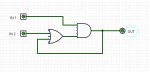
I have studied the manuals but I am still having a hard time writing the code for the attached logic.

Please help
 

Attachments

Odessa

Senior Member
(B+C)*A=C, where "*" means "and"

or equivalently, (A*B)+(A*C)=C

if you connect the output, C to two inverters and call that output "D", then feed it back you can build the following truth table:

ABD C
000 0
001 0
010 0
011 0
100 0
101 1
110 1
111 1

The boolean equation then becomes (B+D)*A=C

The two inverters are for clarification here only; you don't have to actually implement them in your circuit. Make sure that unused inputs on the AND gates are tied high, and unused inputs on the OR gates are tied LOW.

Good luck!

Odessa
 

eclectic

Moderator
@pilko

Welcome to the Forum.

You've posed an excellent question.

Here's a possibility which may help.

Code:
; using 4 as output.

main:
if input1 = 0 then low 4
endif

if input1 = 1 AND input2 = 0 then
low 4
endif


if input1 = 1 AND input2 = 1 then
high 4
endif

goto main
Try the code using the PE simulator.
e
 

pilko

Senior Member
Thanks for your prompt reply I think my attachment is what you're recommending. Now trying to figure out how to write BASIC code for it.
 

pilko

Senior Member
Thanks eclectic. There seems to be a bit of code missing off the bottom of the scrolling window
 

Odessa

Senior Member
Connect input A to Pin1
Connect input B to Pin2
Connect output C to Pin 3
_______________

Code is:

b0=Pin3 or Pin2
b1=b0 and Pin1
If b1=1 then High 3
Else Low 3 EndIf

Takes 20 bytes to implement

Odessa.
 

pilko

Senior Member
Odessa---tried your salution---getting syntax error on line 1 Probably my fault---new at this
 

SilentScreamer

Senior Member
Wont this work?

Code:
Main:
	if pin1 = 1 and pin2 = 1 then Latch
	goto Main

Latch:
	high 0
	do
	if pin1 = 0 then
		low 0
		goto Main
		endif
	loop
 

hippy

Ex-Staff (retired)
An elegant solution is to use pin and bit manipulation ...

Symbol OUT = pin0
Symbol IN1 = pin1
Symbol IN2 = pin2
Symbol TMP = bit0

Do
TMP = TMP | IN2 & IN1
OUT = TMP
Loop
 

pilko

Senior Member
Thanks hippy.It works,I don,t know how.A lot more to learn. Thaks again to everyone,you're a great bunch.
 

westaust55

Moderator
hippy's code works but is not universal. Results in a syntax error on the first line when simulation set to 08M.

But is a lot shorter than the more universal alternative I can up with:
Code:
Main:
	DO
	LOOP UNTIL pin1 = 1 and pin2 = 1
	
Latch:
	HIGH 0
	DO
	
	LOOP UNTIL pin1 = 0
	LOW 0
	GOTO Main
 

hippy

Ex-Staff (retired)
The problem with the code for the 08M is that Pin 0 is output only so "pin0" doesn't exist as a pre-defined symbol. "outpin0" does so this would universalise it ...

Symbol OUT = outpin0
Symbol IN1 = pin1
Symbol IN2 = pin2
Symbol TMP = bit0

Do
TMP = TMP | IN2 & IN1
OUT = TMP
Loop
 

pilko

Senior Member
By the way I'm now tring to figure out all the great codes you guys sent me I'm getting old,it may take me a while (I don't even buy green bananas)!
 
Top