Open collector input or voltage input at the same time?

MartinM57

Moderator
(well not exactly at the same time!)

I'm after a very simple (i.e. elegant) input circuit that allows me to monitor either:
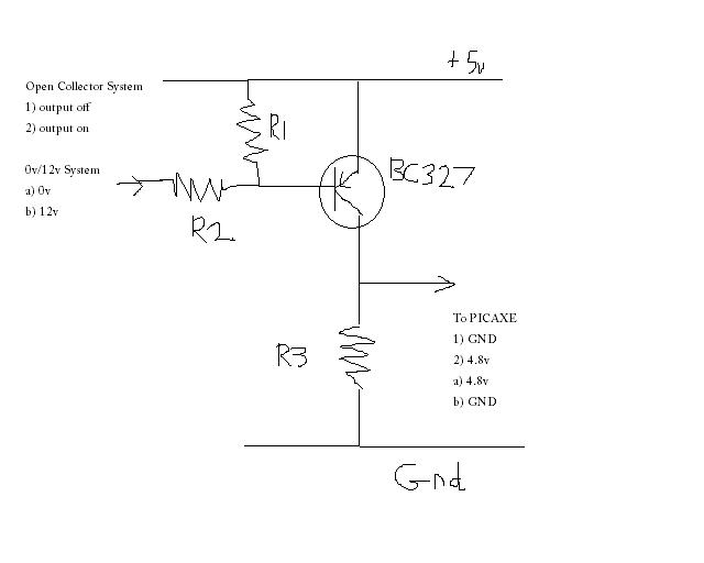
- an external system switching an open-collector output
- an external system providing a 0 or 12v input signal.
...without changing the input components i.e. my system is flexible in that it doesn't care which is plugged in.

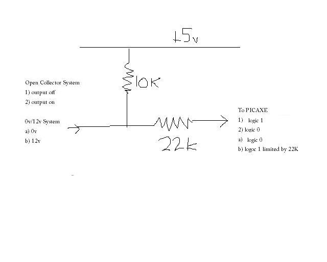
The obvious for the open collector is just a pullup to my +5v supply

The obvious for the 0/+12v is either:
- potential divider
- inline resistor and zener

So can I just combine them to...

Code:
                +5v
                  |
                  |
                  1K
                  |
                  |
input----100R-----------PICAXE
                  |
                  |
             5V1 Zener
                  |
                  |
                 GND
 
Last edited:

westaust55

Moderator
At a glance look, I believe that your suggested circuit should work as intended.

AS Vdd is apparently 5V and inputs ideal should not exceed Vdd, I would suggest using a 4V8 zener and even a 4V5.

Schmidt Trigger inputs are high at >= 0.8Vdd = 4V so whether you are using a TTL or ST input type it will still work with the lower zener voltage and you are keeping within the operating voltage range of the inputs.
 

Dippy

Moderator
I think I've misunderstood re: the sensing a 12V input function.

As I enviasge it:-

1. If nothing is attached to 'input' PICAXE will see input-high as there is +5V applied via 1k res.
2. If 12V is attached to 'input' PICAXE will still see high.
Also, with 12V at 'input' and using 100R I suspect the voltage at PICAXE will exceed 5V1 and also I calculate a current approaching 70mA - not very healthy, but will warm your soul.

This assumes the 'source' resistance of the 12V isn't much. And assumes the 12V side floats when not switched. It'll be fine if the 12V side switches Low when off.
Without knowing the rest of the circuit I wouldn't say this is a good one-size-fits-all circuit and quite wasteful on power.
 

MartinM57

Moderator
You're correct - when the external system is supplying 12v, the input current is 70mA - not good.

Also, if the external system is 'open-collector' and is a ULN2xxxx darlington at the datasheet 1.2v saturation, voltage at PICAXE pin is 1.2 + 100/(100+1000)*3.8v = 1.55v = logic level undefined for either TTL or Schmidt input pin :(

So what is the minimal circuit (passives only) that would be compatible with two different types of external system - maybe there isn't one, if the saturation voltage of the open-collector is 1.2v (although in reality I measure 0.8v which may make things a bit easier...)
 

Dippy

Moderator
Can you clarify the external circuit 'options' - it really isn't clear to me.

Can you draw a couple of 'scenarios'.
 

MartinM57

Moderator
@wa55 - good point.

The PIC16F684 datasheet shows "Voltage on all other pins with respect to VSS ... -0.3V to (VDD + 0.3V)" so a 5V1 Zener is just about OK, but changing it to 4v7 (next preferred value) would probably be better (if the circuit flies at all)
 

BeanieBots

Moderator
I too am a little unclear to the exact requirement but I'm sure an op-amp virtual earth with a few pull-up resistors and/or POT tap with op-amp OP read by an ADC would not only indicate what logic level was connected but also what type.
 

MartinM57

Moderator
Can you clarify the external circuit 'options' - it really isn't clear to me.
Maybe there are 3 external circuits then!

External System Type 1 - Open collector output

Let's say it's built with a darlington driver (with no internal pullup in it)

So output is either open circuit or a switched on darlington that will have a (datasheet) saturation voltage of 1.2v. So if I (just) have a pullup in my system, then I will see either 5v at the input pin ... or 1.2v at the the input pin (which is probably bad news already if I want to detect that as a logic 0)

External System Type 2 - Open collector output

Let's say it's built with a simple transistor driver (with no internal pullup in it)

So output is either open circuit or a switched on transistor that will have a (datasheet) saturation voltage of say 0.8. So if I (just) have a pullup in my system, then I will see either 5v at the input pin ... or 0.8v at the the input pin (which is on the limit for a TTL input to read logic 0 and just about OK for a Schmidt

External System Type 3 - 0v/12v output

It's built with something that gives either 0v out or 12v out


...and I want any of the types of system to be able to be plugged in and reliably read the logic levels (and an input circuit that is made from passives only)
 

MartinM57

Moderator
@BB - unfortunately, the external system (whichever type) is actually supply a variable PWM signal, so I can't use READADC on the input pin as I need to use PULSIN
 

BeanieBots

Moderator
I think a single PNP in normal common emmitter mode at 12v would do the trick. Base held high (turning it off) with pot divider from collector to PICAXE input.
It could probably be jigged to work from a 5v supply.
Base biasing could be used to set any input trip voltage but even without, anything less than around Supply-0.7v would trigger.
 

BeanieBots

Moderator
Now I'm the confused one...fancy trying a bit of ASCII art?
Tried it once, failed miserably:eek:

OK, simple. You are familiar with how to use a NPN transistor as a simple inverter on an input, yes? (or like an LED driver on an output)
It's the same, except upside down and uses a PNP.

EDIT:
Thinking more (difficult at the weekend), you only need the 5v rail.
Just use a highish value base resistor. The transistor will take care of protecting the PICAXE from the 12v signals. Triggering will be happen around 4.5v low and 5v high.
(don't forget, the tansistor will invert the logic which you can take care of in the PICAXE).
 
Last edited:

inglewoodpete

Senior Member
I'll start the debate:
R1=1k ohm
R2=4.7k
R3=4.7k

Input voltage of 4.4 to 12v will not bias the transistor on.
Input voltage less than that should bias the transistor on.

12v in gives an input current around 1.2mA

Breadboard it!
 

MartinM57

Moderator
Breadboarded (but not PEBBLE'd I'm afraid ;))..

Works fine - a few observations though:

- PICAXE input (apart from the linear region - see below) is either 0v or about Vdd-0.05v. So Vce(sat) is about 0.05v? Datasheet says Vce(sat) (max) is 0.7V at Ib = 50mA. Does Vce(sat) reduce dramatically at low Ib values?

- there is a (linear? - didn't measure) region at about 1.6v<Vin<=1.9v where PICAXE input goes between 0v and the Vdd-0.05v - doesn't matter to me as that shouldn't be an input range. But doesn't match wa55's prediction :(

- for External System Type 1/2 (open collector, any technology), when the output stage is switched 'on' the PICAXE voltage is 'high';when the output stage is switched 'off' the PICAXE voltage is 'low'

- for External System Type 3 (0v/12v), when the output is 'on' (i.e. +12v) the PICAXE voltage is 'low';when the output is 'off' (i.e. 0v) the PICAXE voltage is 'high' i.e. a sort of inversion

-...any chance of a circuit that doesn't do the "inversion" between the different types of system as it messes up my PULSEIN - state has to be 0 or 1 to measure the specified PWM widths depending on the type of external system type plugged in and I don't have any means of knowing what type is plugged in

Ta, so far.... :)
 

BeanieBots

Moderator
@Dippy,
The last picture was a real bummer.
Now, where's my strawberries & cream?

@MartinM57,
That's the circuit I was suggesting and you are getting the results I'd expect.
As for the inversion issues, that will be the case no matter what circuit you use.

Should be quite easy to detect which type of input is connected by using an ADC input (via a potential divider) on the input.
If it's 12v/0v, the input will be 12v/0v and can be read by the ADC (as a one off reading).
If it's open collector, the input will only be 5v.

EDIT:
"Does Vce(sat) reduce dramatically at low Ib values?" NO, it goes UP.
However, it does reduce dramatically at low collector currents, which you have. (set by R3).
The circuit inverts for BOTH types of input.
 
Last edited:

inglewoodpete

Senior Member
Oops, slips

- there is a (linear? - didn't measure) region at about 1.6v<Vin<=1.9v where PICAXE input goes between 0v and the Vdd-0.05v - doesn't matter to me as that shouldn't be an input range. But doesn't match wa55's prediction
Hey, It's good when someone else gets the blame when I make a mistake :eek:

A check of my maths suggests that something went wrong.

Vin = 5 - (Vbe * (1k + 4.7k) / 1k) = 5 - (0.6 * 5.7) = 5 - 3.42 = 1.58, which is much closer to the measured value.

I think better with NPN transistors and have to stand on my head to work with PNPs!

Datasheet says Vce(sat) (max) is 0.7V at Ib = 50mA
I had a look at Vishay's datasheet for the BC327 and don't see that value. More like the -0.05v you measured. Refer to chart: "Collector saturation voltage versus collector current", which suggests -0.03v at Ic = 1mA
 
Last edited:

BeanieBots

Moderator
@IP,
Turning the diagram upside down is easier than standing on your head;)
Your sums assume Vbe ~0.6v.
Just like Vce sat, at low currents, in reality it will be a much lower value.
Also, hfe (which can vary considerably from device to device) will also play a significant part.
The response can be made sharper (but closer to 5v) by putting R1 on left hand side of R2 so that Vbe is not subjected to any divider action.

@MartinM57,
The sole purpose of the transistor in this application is to shift the switching point further away from 0v so that a darlington connection (which could be as high as 1.2v) will be seen as a logic zero. The linear region you see is expected but it is much smaller and closer to 5v than without the transistor.
The inversion effect will be identical for either type of input.

If you need to change your code depending on which type of input is connected, you will need to use a another input. You can tell which type of input is connected quite easily. A darlington will be pulled up to close to 5v, a 12v input will be 12v. So, by testing the logic high voltage, you can determine which type of input is required. To do this transparenty in hardware would be far more complex but I'm sure it could be done with a handful of transistors or a couple of op-amps.
 

MartinM57

Moderator
So I've now found that the open collector external system pulls down to very close to ground as the current is very small. So I can just simply use a variation of the simple programming circuit...


...can't I?
 
Top