westaust55
Moderator
Using the DS2408 as a 256 step DAC
Just when folks thought it was safe to go back in the water . . .")
I have done some trials using a DS2408 1-Wire 8-channel PIO as a DAC since the DS2890 digital pot IC is no longer readily available.
A couple of things to note are:
1. THE DS2408 outputs are open collector and so will not pull a line high so we must use a pull up resistor
2. The open collector pins only pull the lines down to around 0.03 volts when the current is 0.4mA and around 0.13 volts when the current into the pin is 2.2mA.
I have tried a couple of different variants based upon the basic R-2R network. One ignored the above points and the other tried to compensate for the above mentioned points.
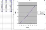
The end result is that a moderately reasonable DAC output was created that was monotonic (ie as the data value increased the analogue voltage rose at each step) but the analog value was not exactly linear even though some care have been used with 1% MF resistors and check individual resistor values.
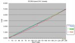
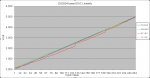
The attached chart from Excel shows the approx DAC output voltage as the value is increased.
- The pink line ignores the mentioned effects entirely
- The blue line tried to do some compensation
- the green line is a straight line representing the theoretical voltage output
I will attach some further details of the R-2R resistor networks and may try a few more resistor "tweaks" shortly.
Just when folks thought it was safe to go back in the water . . .
I have done some trials using a DS2408 1-Wire 8-channel PIO as a DAC since the DS2890 digital pot IC is no longer readily available.
A couple of things to note are:
1. THE DS2408 outputs are open collector and so will not pull a line high so we must use a pull up resistor
2. The open collector pins only pull the lines down to around 0.03 volts when the current is 0.4mA and around 0.13 volts when the current into the pin is 2.2mA.
I have tried a couple of different variants based upon the basic R-2R network. One ignored the above points and the other tried to compensate for the above mentioned points.
The end result is that a moderately reasonable DAC output was created that was monotonic (ie as the data value increased the analogue voltage rose at each step) but the analog value was not exactly linear even though some care have been used with 1% MF resistors and check individual resistor values.
The attached chart from Excel shows the approx DAC output voltage as the value is increased.
- The pink line ignores the mentioned effects entirely
- The blue line tried to do some compensation
- the green line is a straight line representing the theoretical voltage output
I will attach some further details of the R-2R resistor networks and may try a few more resistor "tweaks" shortly.
Attachments
-
 61.4 KB Views: 59
Last edited: