Thanks BeanieBots,,, I cant do much right now as I am in the office.. But if it helps, I did do some more "playing around" last evening.
The aim is to find a solution to the wretched TB6560 "power up" "power down" sequence.... In fact I dont know why I am bothering to simulate it, because I already have the answer in my head.. Simply apply 5v to the logic 1st and simultaneosly to a 5V relay. The relay then switches 24v through to the motor drive pins.. I also intend to hold up the logic with 20uF or something... Maybe some low impedance across the 24V to make sure that the Elctrolytics upstream discharge quickly in the case of sudden mains failure.
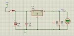
Anyhow, way off topic. So having had VSM for all of 15mins, yet familiar with Lspice and ISIS, I added a 5v regulator to a blank canvas.. ( it didnt seem to mind which reg was used).. I then added a 5V relay. Finally an interactive switch.
Ground and 12V terminal.
When I first saw the problem, (relay didnt turn off) I added a probe to the 5V output.. I noticed that the 5V went down to 1.93V after the switch (input side of regulator) was forced "off" ... Then I researched the relay and see that it has a min drop out voltage of 1V.
So that explained why the relay wasnt turning off.
Then I thought well maybe I havent met the real life conditions expected around a regulator and that VSM behaved the same way.
So I started adding decoupling caps 100n and also 10uF, just as it you had a real life scenario, still the same.. So I added a low impedance load (100 ohm) across the output of the reg.. Still no luck.
At which point I gave up.
However, if the DVM is left in place across the output of the regulator and the circuit iis "run" with just the "pl;ay" and "stop" buttons..... then the cct behaves as expected.. The DVM drops back to 0V.
When the interactive switch is inserted between 12V terminal and Reg input, the cct is made to "run" and just the momentary switch is used to switch power through to the reg or not... then I see the problem, the ouput of the reg never falls back to zero..
So I guess the cct with all of 4 components is wired correctly since it simulates ok with RUN/STOP, but then I suppose the DVM will display sero, since in the stop mode it is no longer simulating.
When I get home I will post the cct.
Thanks