As Westaust55 has suggested the best way would be to have the picaxe set up as a basic I/O mother board with all the I/O pins connected to header pins on the mother board along with 5v and ground (3 pin header for each I/O pin) then have all your add on circuits built on sister boards that simply plug/connect to the 3 pin headers as needed, this way if you want a mat switch you just add the sister board for that application, if a IR beam is required you add a IR beam sister board, etc, this way it becomes a plug and play system making it very simple for anyone to add or subtract different modules (sister boards) to create any effect that is required, it also keeps everything the same for each group member allowing them to teach each other.
This way much of the code needed for the sister boards will often be almost the same, and allow a lot of cut and paste of sections of code with a few tweaks to suit the application.
I done this method for a data logger system that allowed simple circuit changes to be made by just adding a sister board to suit the input requirement, it was far easier to just design several small circuit boards to suit each sister board requirement, than it was to redesign the whole main circuit board each time different application was needed.
One thing i do when making a general board design is to always reserve the I2C pins unless i absolutely need to use them, because there is often times later you can make use of I2C on a board and to simply have a connection point can save a lot of time redesigning a new board to suit, i know you said I2C was beyond your present skills, but you will soon find it easy once you need to use it.
Things like needing to add a RTC will need I2C, and huge range of other devices.
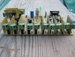
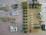
On the board below I2C is the 4 pin white headers in the middle.
I used double row headers for strength in mounting of the sister boards, and also a second header not connected to anything for extra support as they are only cost a few cents.