Newb help needed please

Keith35

New Member
Hi,

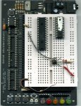
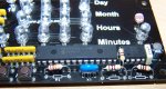
I got the AXE114S binary clock kit for Christmas and have carefully spent a month putting it all together. I've had my ups and downs as i haven't soldered anything for a long time, but i think i got it right. I've been over the board loads of times and checked the solder and it all appears fine.

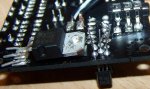
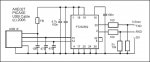
It uses a PICAXE 28X, with a 9V power supply which is regulated by a device on the board. I have checked the voltage between pins 8 and 20 and between 19 and 20 and in both cases it's 4.98

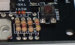
I have checked the 1K and 22K resistors as well and they are all fine.

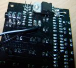
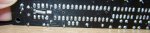
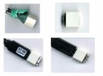
It was working OK, but when i unplugged the USB cable, it went wrong and seemed to light up LEDs at random and now i can't even download a new program to it. I get the "HArdware not found" message, or when i do a reset, i get "Memory Verification failed".

i think both these messages come from a failed Chip, so is this the most likely cause and what else can i do to rule it out?

Cheers,
Keith
 

hippy

Ex-Staff (retired)
Welcome to the PICAXE forum.

First thing to try is a "hard reset". Power-down your board, start a download then when the pop-up shows "Connecting to hardware ..." turn the power back on.
 

Keith35

New Member
thanks. I've already tried that a few times and got the "memory verification failed" message.

just wondering, what are the chances that it's a problem with the USB cable? I'm using the one that came wiht the kit, but it is behaving oddly. When i plug it in to the USB port, it shuts down my computer (as though there's a power surge). this happens whether or not the USB cable is attached to the PCB.
 
Last edited:

kevrus

New Member
In your first post you mention a 1K and 22K resistors. If you are referring to the download resistors, then it should be 10K and 22K...maybe worth checking the values unless its a typing error.
Standard colours for 4 band colour codings are:
10K.........brown/black/orange + tolerance band (gold for 5%)
1K...........brown/black/red ....................ditto
22K.........red/red/orange ......................ditto
 

hippy

Ex-Staff (retired)
@ Keith : It is odd that the USB cablse should be shutting down the computer. This could be causing later problems. Do you have another PC to try it with or a friend who will let you try on their PC ?
 

Keith35

New Member
hmm, don't know if they are download resistors (I said i was a newb :confused:), but they are defintiely 1k, as per the product datasheet: http://www.rev-ed.co.uk/docs/axe114.pdf

Tried the USB cable on my laptop. It didn't shut the laptop down, but still no joy downloading - i get the same error messages.
 

eclectic

Moderator
@Keith.

There isn't a schematic available, so, could you provide

high quality jpg photographs of each side of your board, or

a flatbed scan of each side of the board?

e
 

BCJKiwi

Senior Member
@Kevrus, Keith;
Looking at the picture in the axe114.pdf, and in the absence of a circuit diagram, one would have to assume that the download circuit resistors are the 22k R1 and one part of the A5 10k resistor array which appears likely from the board layout.

Definitely suspect a fault in the USB cable/USB port. Plugging in the cable should not shut down the PC.
Does that same USB port work OK with other USB devices?
Does the cable cause the same problem if plugged into another port?
 

westaust55

Moderator
AXE114 Binary Clock datasheet

Having looked at the datasheet, I was astounded to be greeted on the last page of a document created in late 2008 with:
"Appendix B - Circuit Diagram to be added"

How on earth is a newbie (and likely many others) supposed to know how the hardware side of the circuit works! :rolleyes: Sure the board has markings for each reisitor but what are they doing?


It is likely that the 10k Ohm resistor may be an element in the 10K Ohm resistor pack. Likewise for the i2c bus two of the resistors in th 4.7kOhm resistor pack would be used.
 
Last edited:

Keith35

New Member
thanks for your help everyone.

first, i connected the cable to the neighbouring (front) port and it shut down again

then, i connected the cable to a USB port at the back of my PC, which is on a different card, and the PC didn't shut down.

i have tried all my other USB devices in the front port and nothig else has shut it down. i'm pretty sure the front ports are connected to the motherboard and the back ports are on their own PCI card, whuch leads me to think that the cable is causing the PC to detect a power surge (a PCI card will have surge protection built in, right? the motherboard will have surge protection of it's own, next to the power supply, but not neccesarily next to the USB) and shut down.

there's no point in sending photos of the circuit board since all the connections are underneath a coating and it'd be impossible to make them out in a photo.


thanks again all.
 

eclectic

Moderator
there's no point in sending photos of the circuit board since all the connections are underneath a coating and it'd be impossible to make them out in a photo.


thanks again all.
Sorry Keith, what I meant was photographs to show your soldering connections.

e
 

eclectic

Moderator
How detailled and what do you want to see? I'm not supposed to post large photos on here, am i?
As detailed as you can make it.
To see the soldering and anything that might help.


The original photographs / scans for the pic's I've attached, were Megabytes.

The first one was taken using a cheapish Digital Compact camera.
The second was taken using a cheapish Epson Flatbed scanner.

I reduced them using Adobe Elements.
("Save for Web" option.)

Plenty of alternative programs / cameras / scanners available.

e
 

Attachments

Last edited:

lbenson

Senior Member
As brought up by kevrus, there's the question of whether the download resistor is 1K or 10K. Both R2 and R3 are 1K--what are they supposed to be?
 

Keith35

New Member
according to the datasheet, they are both supposed to be 1K. best guess is that the 10 k resistors are in one of the arrays.
 

Andrew Cowan

Senior Member
A5 is a 10K array.

Keith - it might be worthcutting the legs of the soldered components to make sure they don't touch together and short out.

A
 

westaust55

Moderator
A5 is a 10K array.

Keith - it might be worthcutting the legs of the soldered components to make sure they don't touch together and short out.

A
Thats what is mentioned in the last sentence of post 9.

But, not sure why one might want to cut the legs of the SIL resistor pack. Can you expand on this idea/purpose
 

Dippy

Moderator
Looks like they have touched already....

ALL excess stuff should be chopped off before testing/powering.
It REALLY is ASKING for trouble.

I don't know what the transistors do in this circuit - as pointed out there is no schematic apperent to my Ebay eyes.
I don't know how robust the USB cable is, but is there a chance that Q1/Q2 legs touching could have damaged the USB cable? Or other things touching maybe? e.g. regulator tab?

BTW: Have you actually go the USB cable working yet?

(PS. I confess that I'd never heard of a resistor 'pack' before. Is that an old fashioned term? Most peeps call it an 'array' or 'network'. To me, a 'pack' is a polythene bag stuffed full ;) . I see that term gets used on Ebay a lot...)
 

Andrew Cowan

Senior Member
Considering how much ebay annoys you, you seem to spend a lot of time getting to know it :)

Hooray - I can finally tell you to read the datasheet!

Code:
Transistors Q1 and Q2 control which set of LEDs is displayed at any one time.
A
 
Last edited:

Dippy

Moderator
True. To bring joy to others brings happiness to my soul. Though, in reality, I did actually mean how they were connected in the schematic.

I googled "resistor pack"and Ebay came up a lot.
I was trying to find if it was a geographically-related phrase as I'd never heard of it before.
It's not important.

More importantly, has the USB cable issue been sorted? Can an unfortunate 'moment' with legs touching have damaged it? I really don't know. It appears the cable wasn't DOA. This could be important for Keith and others.
 

Keith35

New Member
there is a cahnce that one of the capacitors was touched by the tab of the power regulator. I unsoldered the powe regulator and moved it a little to be furhter away.

However, the problem i have is still that i can't download anything to the PICAXE chip, despite the regulator providing a constant 4.8 v to the chip. surely the capacitors wont continue to cause this problem, will they? Also, it doesn't explain why the USB cable makes my PC shut down.

thanks
Keith
 

moxhamj

New Member
There are several steps to work through if it doesn't download. First thing is the download cable. It is most concerning it is shutting down the PC - but anyway, plug it into the board, and get a volt meter and put the negative on the earth somewhere on the board and measure the volts on each of the 3 pins on the socket. You should get -9 or -12V on one of them. If you can tell us those voltages that is a start.

Next is to measure the volts on the download pin of the picaxe. But measure the volts on the 3 pins above first.

We may then need to go off on a bit of a tangent and build a loopback circuit and test it with hyperterminal to see if the problem is the download cable or the picaxe board. But the PC shutting down suggests a zapped download cable with an internal short.
 

BCJKiwi

Senior Member
Are you able to download when using one of the rear USB ports (which don't shut down the PC?). You will have to change the associated com port/USB port association for PE to work on the new USB port.
 
Last edited:

Dippy

Moderator
Doc, he said he's using the USB-serial.
You may like to update your test?

I would do some continuity tests on the PCB with PICAXE chip pulled out.
Trouble is that if a brief touch of leads caused the problem then a short (or very low R) may not show up.
Maybe PICAXE damaged too?

Seems like 3 main possibilities.
1) USB cable broken.
2) Ditto PICAXE
3) Faulty PCB (maybe only temporarily due to legs touching!! Or cockup soldering?)

I'm not going to ask WHY you didn't chop the excess off, but instead suggest :
1) Do a test like Drac suggested (sans PICAXE) but look for 5V (for a USB-serial converter).
2) Check continuity on your board. i.e. make sure there aren't any shorts where they shouldn't be. (This isn't helped by the lack of a schematic, but any pin, apart from ground, showing <470R to ground is to be suspected at a guess).
3) Do another visual check of your board with a good magnifying glass.
4) With PICAXE still removed and serial disconnected, measure power consumption of board.


Problem is that you really need a scope to do (1) properly, an LED+Res will indicate activity but you need a scope to get levels and timings.

What would I do if I didn't have a 'scope?
1. Use an LED+R on the jack plug, and try a programme download. If the LEDdoesn't flash at all then we have a problem Houston.
2. Do you have a PC with a genuine RS232 serial port? - a 9 pin D shaped thing? After I had checked that there were no problems with the serial connection on the board and that contniuity to the PICAXE was OK, I'd get another USB-serial AND the lower-cost Serial-jack lead, AND another PICAXE AND the cheapest project board.
Some may to use plug-in breadboard, but I think the safest is to make up the cheapest project-board and try a download.
I DO hope you'll chop the excess leg/lead off the next time ;)
Maybe the whole lot will just go in the drawer?

Some, (Stan), prefer doing it on breadboard. That's probably what I'd do too, but I have seen many cockups; resistors crossing etc. so I can't quite advocate it for total newbies (no offence, I'm thinking of your wallet).

And I take it you tried the USB-Serial on an ex-friend's PC too?
 

slimplynth

Senior Member
going on a maplins holiday

It's like Crime Scene Investigation - Picaxe: and I like it :)

If i spent half as much time tinkering as I do reading about other people's problems, maybe my desk would have something (picaxe related) decent on it.
 

eclectic

Moderator
Another possible test method?

I used a bare USB socket from an old hub.
(Also possible with a flying socket, and exposed leads. )

I also used the AXE027 schematic from page 11
http://www.rev-ed.co.uk/docs/axe027.pdf

The USB “A” wiring is Gnd .. D+ .. D- .. V+

Plugged in a new, working, AXE027.

Results.
Stereo tip > USB gnd < 1 ohm.

Stereo tip >> Ring c.9.9 K
Stereo tip >> Sleeve c. 9.9K

USB end.

Gnd > Data+ = c.7.3 M
Gnd > Data- = c. 7.2 M
Gnd > V+ = c. 5 M

And the lead still works.

Much faster to do, than to write.

e
 

Attachments

Keith35

New Member
Ok, you've lost me with "hyperterminal and "LED+res", but from what i cna gather, the first thing i need to do is remove the PICAXe Chip, then plug it in to the mains and connect the USB as if i were about to download the programs. Once that's all connected, I've got to test the voltages between anywhere on the board that says 0v and the 3 legs of the stereo Jack.

I've also got to test the resistances between 0v and each of the legs.

I've only got a digital multimeter, so i think i'll have to leave it at that for the time being...

Can you let me know if that's right, and i shall do it tonight.
 

Andrew Cowan

Senior Member
Ok, you've lost me with "hyperterminal and "LED+res", but from what i cna gather, the first thing i need to do is remove the PICAXe Chip, then plug it in to the mains and connect the USB as if i were about to download the programs. Once that's all connected, I've got to test the voltages between anywhere on the board that says 0v and the 3 legs of the stereo Jack.

I've also got to test the resistances between 0v and each of the legs.

I've only got a digital multimeter, so i think i'll have to leave it at that for the time being...

Can you let me know if that's right, and i shall do it tonight.
Sounds good.

A digital multimeter is the best sort.

LED+res = an LED, and a 560 ohm resistor. (Could be other values, but 560 is a safe starting point.)

A
 

Keith35

New Member
As it goes, i have got a dead PC that i am going to install Linux on... one day! I could use that.

Is this test going to kill the USB card?
 

eclectic

Moderator
No stop!

Literally, just a socket,

taken from a spare extension lead
or 4-port hub

I'll tryand get a photo asap.

e
 

Keith35

New Member
e,

A quick dig around in my desk uncovered a PS/2 -USB adaptor. If i hack that apart (it's in a moulded case), will that do, do you think?

Cheers,
Keith
 

eclectic

Moderator
I've also just found one.
My AXE027 cable plugs into the USB end.

I can't tell you what to do but, if you're willing to try,
then have a go at taking it apart.

e
 

eclectic

Moderator
Fiddly or what??

I had a go at chopping up my PS2/USB adapter.

I plugged in my AXE027 to the "socket"

Crocodiled the tip of the stereo pin, to one input of the multimeter.

Tested each of exposed connectors.

1. Less than 1 ohm (the gnd)

2, 3, and 4 = MegOhms.

e

Remember. Your property and your decision.
 

Attachments

Top