New little Project

craig008

New Member
Hey All
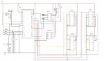
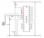
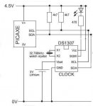
Its been a while since i have had chance to do any picaxe, or vary much else for that matter. I was thinking about making my an LED alarm clock using some 7 segments displays, 4026s, DS1307 and driven by either a 28X or 18X.

http://www.maplin.co.uk/module.aspx?ITAG=SPEC&ModuleNo=2166&doy=21m5#spec

these are the displays i am going to use in a comon cathode package. i was thinking it would be easier to use a single resistor on the comon pin of each 7 segment and providing i got my maths right it would mena i would only need a 23 ohm resistor. is the a good idea to use the comon pin or should i use individual resistors for each LED? i supose the this makes more sense as the output of the driver will change depending on how many LEDs are lit up.

as for other precautions should unused legs of the 4026B by tied low with a 10K resistor to stop them from floating? will pull down/up resistors be need for the clock and reset pins of the 4026Bs' (these pins will be connected to the picaxe)?

thanks for any help
________
Buddhism Advice
 
Last edited:

Mycroft2152

Senior Member
G,

The problem wth using a single resistor per digit is that the LED brightness will vary with the number of segments lit on each display. Best practice is to use one resistor per segment.

Or else use a driver chip with a constant current source per segment.
 

marcos.placona

Senior Member
"as for other precautions should unused legs of the 4026B by tied low with a 10K resistor to stop them from floating?"

Not necessary. You ain't gonna have many pins left anyway
 

craig008

New Member
thanks for your inputs, i will be looking at resistors in dil packages for ease of use and construction.

http://www.datasheetcatalog.org/datasheet/SGSThomsonMicroelectronics/mXyzvsrs.pdf
i found this data sheets which points out some interesting facts of the 4026B. the one i am most interested in is the display enable (pin3). it appears that if power is removed from this pin all of the segments of the display will switch of while leaving the chip active to display the correct number (like an on/off switch for the display part). would this observation be correct and if so would it be possible to control this through a transistor (thism means i can make the display flash when the alarm goes off)
________
New jersey dispensaries
 
Last edited:

hippy

Technical Support
Staff member
You should be able to control the display enable direct from a PICAXE I/O line or with a switch to +V or 0V with a pull-up or pull-down as appropriate if you wanted manual control. No need for a transistor.
 

craig008

New Member
so in that case i could connect out 7 on the picaxe strait to pin 3 of the 4026 allowing the high command to switch on the display and a low command switching it off. would this still be the case when 4 4026s' multiplexed together (2 pairs, one pair for the minutes and one pair for the hour)
________
The Office Dicussion
 
Last edited:

hippy

Technical Support
Staff member
Yes ... just take the Output 7 to all the 4026's display enable input ( pin 3 ).

There's also a display enable output ( pin 4 ) so you could drive just one 4026 and link its pin 4 to the next digit's pin 3.
 

craig008

New Member
OK thanks for that hippy, it will be easier to hook up and test like that (connect pin 4 to pin 3of the next chip)
________
Grape ape
 
Last edited:

inglewoodpete

Senior Member
All input pins on a CMOS chip MUST to terminated. CMOS chips are easily damaged by having inputs open circuit, especially in low humidity and thundery conditions.
 

Michael 2727

Senior Member
The 4026 chips will drive each segment/s with around 4mA, @5V DC
without the need for any resistors. (internally limited to some degree)
This is bright enough for most indoor displays.
 

craig008

New Member
All input pins on a CMOS chip MUST to terminated. CMOS chips are easily damaged by having inputs open circuit, especially in low humidity and thundery conditions.
OK so pins 5 and 14 need to ties low with 10K resistors or will just a strait wire jumper do the job

thanks Michael i was just about to have a look at the resistors before i got started
________
Smoke Weed Every Day
 
Last edited:

inglewoodpete

Senior Member
I think the specified resistor on an input to a CMOS chip is 220k but I don't know why. Almost any value less than that should be OK. I have used 220k, 100k and 0ohm myself in the past.
 

hippy

Technical Support
Staff member
I'd take them direct to 0V unless somone could come up with a good reason why not.
 

craig008

New Member
OK got the diplay circuit up and nrunning, no tie downs seem to be rquired, ir runn as smooth as you like. now i have to the more complex part of the project - I2C.

what is the best voltage to run it at 4.5 (3 aa batterys). i have the clock hooked up, i think i made a mistake when i first ut it together and had the the 1Hz LED hooked to the supply pin (pin 8). i am not sure if this would have fried the chip or not but i dont seem to be getting much out of it

is this programme going to be OK for testing it providing the circuit is correct?

symbol sec = b7
symbol mins = b8
symbol hour = b9
symbol day = b10
symbol date = b11
symbol month = b12
symbol year = b13
symbol control = b0

init:
hi2csetup i2cmaster, %11010000, i2cslow, i2cbyte


let sec = $00
let mins = $59
let hour = $11
let day = $03
let date = $25
let month = $12
let year = $03
let control = 16

hi2cout 0,(sec,mins,hour,day,date,month,year,control)

main:
hi2cin 0,(sec,mins,hour,day,date,month,year)
debug
pause 1000
goto main

thanks for all your input so far guys it is appreciated
________
Ford Ranchero Rio Grande History
 
Last edited:

eclectic

Moderator
Grapes.

Have you read the i2c guide?

(Prog Editor >> Help >> Picaxe 28/40 datasheets)

There's a lot of help in there, especially
on page 7.

e

Apologies if you know already.
 

westaust55

Moderator
Firstly I reiterate what InglewoodPete has stated.

CMOS logic such as the 4xxx requires ALL unused inputs to be tied high or low.

Background = CMOS inputs have two transisitors and in the high or low state only one will conduct. However when the inputs are left floating, both transistors can conduct resulting in high currents (several milliamps) which can damage the inputs. Worst case is when inputs are around 1.5V.
The datasheets specify a transition time so that very little time is spent in the undefined voltage range when switching from one valid state to another to avoid such damage.

Secondly, the i2c comms bus should work perfectly okay whether on 4.5V or 5Vdc.

The 4026 chips will drive each segment/s with around 4mA, @5V DC without the need for any resistors.
The 4026 is not designed to drive LED's directly. You should use either buffer ICs or transistors.
The datasheet (see page 7 of attached file) indicates the outputs can only source and sink around 1mA (in fact can be far less) current. Therefore 4mA is well into overload.
 

Attachments

Last edited:

craig008

New Member
i have just soldered some grounding jumpers for the 4 4026s'. i hvae been using 5v so thats fine, the problem was a short between 2 pins (sda and scl). now i hust have to figure out how to use the 24cl16 with the new commands.
________
Medical marijuana strains
 
Last edited:

Rickharris

Senior Member
...
The 4026 is not designed to drive LED's directly. You should use either buffer ICs or transistors.
The datasheet (see page 7 of attached file) indicates the outputs can only source and sink around 1mA (in fact can be far less) current. Therefore 4mA is well into overload.

Every source I can find shows the 4026 driving 7 seg CC displays directly - indeed many practical projects we have built also do so quite happily.

The IC is intended to be a counter 7 seg display driver so why wouldnt it?
 

westaust55

Moderator
I had a look at the SGS Thompson 4026 datasheet as well and also has examples showing transistors to interface.

I would be interested in seeing a datasheet that shows direct conenction of LEDs to 4026 outputs. Could pass that on to some component suppliers here.

However when it comes to getting some light out of an LED, a "normal' (not superbright type) LED will illuminate at around 0.3mA albeit that the brightness is in the dull category compared to around 8 to 10mA that I usually use.

EDIT:
From the datasheets, with respect to the output current of the 4026, the 4026 can operate at a voltage in the (recommended) range from 3V to 20V.

For the ST version of the 4026B the available/max output current is 1mA at 5V supply and is 2.4mA at 15V supply.

For the SGS version of the 4026B the available/max output current is 1mA at 5V supply and is 2.6mA at 9.5V supply and is 6.8mA at 15V supply.

The above does not preclude people from using the 4026 (or any IC for that matter) outside the design parameters.
 
Last edited:

samant

New Member
I am new and need help

Hi everyone,
I am doing a project using picaxe 28.the program starts by reading a Temp. sensor. i have attached two motors to the mptor output A&B, i want to move this motors back and forth for a certain distance starting from the center until they received a signal from another sensor. when they receive a signal from the sensor i want them to move back to the orignal position, which is the center, would you please anybody help me how to program this.
Here is a rough diagram.
position (A)
position (B)
position (C)
Motor (M1)& (M2)

(C)
(A) <--------------------->(M1)<----------------------->(B)
<--------------------->(M2)<----------------------->

Moving (M1)&(M2) to (A) and again to (B) & again back to (A) & to (B)
when sensor 2 gives signal both motors back to position (C) from anywhere they are.
Thanking you in advance this will be very helpfull for my prototype project.
Thanks again
Samant (new user)
 

craig008

New Member
OK i think i have some sort of problem at the mo

hi2cin 0,(sec,mins,hour,day,date,month,year)

this comand seem to reset the chip, within this programme, have i got somthing wrong

Code:
symbol sec = b7
symbol mins = b8
symbol hour = b9
symbol day = b10
symbol date = b11
symbol month = b12
symbol year = b13
symbol control = b0
symbol temp_byte = b1

init:
	hi2csetup i2cmaster, %11010000, i2cslow, i2cbyte
	debug
	let sec = $00 
	let mins = $59 
	let hour = $13 
	let day = $02 
	let date = $27 
	let month = $05 
	let year = $08 
	let control = %00010000
	debug
	hi2cout 0,(sec,mins,hour,day,date,month,year,control)
	pause 20
	
main:
	hi2cin 0,(sec,mins,hour,day,date,month,year)	'suspect command
	pause 20	
	sound 6,(120,30)	'check to see if it passed previous command
	gosub bcd_decimal
	debug
	goto main
	

bcd_decimal:
	sound 6,(150,50)
	let temp_byte = sec & %11110000 / 16 * 10
	let sec = sec & %00001111 + temp_byte
	let temp_byte = mins & %11110000 / 16 * 10
	let mins = mins & %00001111 + temp_byte
	let temp_byte = hour & %11110000 / 16 * 10
	let hour = hour & %00001111 + temp_byte

	let temp_byte = day & %11110000 / 16 * 10
	let day = day & %00001111 + temp_byte
	let temp_byte = date & %11110000 / 16 * 10
	let date = date & %00001111 + temp_byte
	let temp_byte = month & %11110000 / 16 * 10
	let month = month & %00001111 + temp_byte
	let temp_byte = year & %11110000 / 16 * 10
	let year = year & %00001111 + temp_byte
	return
 

eclectic

Moderator
grapes.
re.your post #19
i have just soldered some grounding jumpers for the 4 4026s'. i hvae been using 5v so thats fine, the problem was a short between 2 pins (sda and scl). now i hust have to figure out how to use the 24cl16 with the new commands.
Please, can you provide the circuit diagram, and,
some high definition photographs, if possible.

e
 

BCJKiwi

Senior Member
Try without the debug entries.
Use sertxd of the values you want to check instead.

There is sometimes interaction with debug and the program flow.
 

craig008

New Member
here are some pics.

the use of the sertxd command didnt work, and the comand isnt performed even when there is no I2C device in the circuit. I am think i may need some sort of smoothingto allow the circuit to operate.
________
Yamaha td2
 

Attachments

Last edited:

BCJKiwi

Senior Member
Well there is the oft quoted need to tie all the unused inputs low to stop them floating.

That means a separate 10k to ground on legs 2,3,4,5 and 16,17,18.
Also there is the equally oft quoted need for filter caps on each supply at the chips - particularly the 28X1. As you've not indicated where the 5V is coming from, the need for these is not clear - others will doubtless have a better idea of what noise might be generated by the 7Segs/drivers.
 
Last edited:

craig008

New Member
I have a bunch 100uf (some 1uf) electrolitic, will they be OK? would these floating pins cause this problem, i have never had any problems before.

i will fire up the soldering iron and start getting those reistors in anyway, thanks for your help.
________
Ford 335 Engine History
 
Last edited:

BCJKiwi

Senior Member
The filter caps are much smaller typically 100nF and right beside the chip - not just any convenient place.

You are correct to query if these are needed as most get by without. However it is recommended good practice and obviously improves reliability.

As there is nothing obvious wrong with the code or circuit (as far as I have seen after a quick look) it is worth a try.
 

BCJKiwi

Senior Member
Taking another look at your program, I see there is no code relating to the eeprom chip. Have you tried running the circuit without the eeprom chip as it is not initialised and may be upseting the i2c bus.
It is quite likely that this comment is not relevant as I've not used one of these eeproms and therefore do not know how they behave if not initialised.
 

craig008

New Member
yes, that is all i have been doinf until i can the bugs worked out. i will do the same for the eeprom, remove the clock and make sure that part of the circuit works fine. the programme resets even with no I2C device.

Is there a particular kind of capacitor that is bes suited to the appliction of chips?
________
CHRYSLER E PLATFORM
 
Last edited:

eclectic

Moderator
grapes.

Some longwinded thoughts.
Simply adding to BCJ's advice.

1. Get a breadboard and some turned pin sockets.
2. Build a minimum 28X1, plus 10k resistors to ground.
3. Add a 100nF "box" type capacitor near the inputs.
4. Check the circuit is working, by downloading a simple program.

Then,....

5. Add a simple DS1307 circuit.
6. Add a 100nF capacitor near +V and gnd.
7. Make sure you've got a 12pF crystal properly connected.

Check ALL the connections.

In program Editor >> Picaxe >> Wizards >>AXE110 Datalogger >>
Set DS1307 Date/time.

Change
Code:
ok:
	high 3
	goto ok
fail:
	high 2
	goto fail

to

ok:
sertxd ("working",cr,lf)
goto ok

fail:
sertxd ("fail",cr,lf)
goto fail
Run the program

If OK then you're on your way.

e
(If I've made a typo in this lot, I apologise in advance.)
 

Attachments

craig008

New Member
i cant get box capacitors that small donw here very easily , i now have 100nf polyester and 100nf electrolitic.

i will make that circuit up now, i will use a slightly modified (jumper put in place of drive IC) 28 starter board ans see what happens

oh nearly forgot, do i need that 3v cell battery for the test circuit??
________
Los Angeles Dispensaries
 
Last edited:

craig008

New Member
there is a problem with the download circuit on the board i have made up, if i programme on the proto board it works fine, then once its transfered it stops sending data back. alos if i programme on the bord i made and then put the chip in the proto board i dosnt send info back.
________
Ford bronco
 
Last edited:
Top