My DMX Receiver Project
Hi, I'm currently using an X2 PICAXE (the 40X2 in my case, but the 28X2 may have been suitable if I'd been less ambitious with other needs) to act as a DMX -> 1-10V converter (to replace a secondary 1-10V fader we have and put that lighting onto our main DMX desk) and I thought I'd share my experiences in case they're of interest to anyone else wanting something similar.
First, I needed a DMX receiver. I'd seen this (http://www.picaxeforum.co.uk/showthread.php?20580-DMX-Data-Receiving-using-28x2-100mhz) which was a good starting point.
But, the problem I saw was that the break detector would give false triggers if it started during a DMX packet. This means that if the timing goes out, rather than waiting for the next packet, it will get bad data before recovering. In our situation that could be bad.
So, my thought was to build a simple hardware break detector (you don't need to detect the 'make after break', because the make is just an idle line) and wire that to one of the hardware interrupt lines on the PICAXE
The attached schematic shows the circuit I used for the break detector. You could possibly use a diode OR gate instead of the 74LS32, but I had another use planned for that IC in the overall circuit, so I decided to use that.
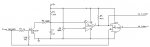
The basic idea is that when the serial in is high, Q1 grounds C1, then when the serial in goes low, the capacitor charges (I needed R6 because the low output of the MAX485 is sometimes just over the base threshold of Q1 so I got some leakage through that for a start). By adjusting the pot (R4) you can get it so that the comparator causes a high signal after the serial in has been low for 48uS (indicating a break, rather than a 0 data byte), then that stays high until just after the break ends. The comparator output can go to a hardware interrupt pin (to detect a rising edge) and is ORed with the serial to make the break shorter and the mark longer
Hopefully this would give enough time for the PICAXE to get ready for the incoming data which follows
Hi, I'm currently using an X2 PICAXE (the 40X2 in my case, but the 28X2 may have been suitable if I'd been less ambitious with other needs) to act as a DMX -> 1-10V converter (to replace a secondary 1-10V fader we have and put that lighting onto our main DMX desk) and I thought I'd share my experiences in case they're of interest to anyone else wanting something similar.
First, I needed a DMX receiver. I'd seen this (http://www.picaxeforum.co.uk/showthread.php?20580-DMX-Data-Receiving-using-28x2-100mhz) which was a good starting point.
But, the problem I saw was that the break detector would give false triggers if it started during a DMX packet. This means that if the timing goes out, rather than waiting for the next packet, it will get bad data before recovering. In our situation that could be bad.
So, my thought was to build a simple hardware break detector (you don't need to detect the 'make after break', because the make is just an idle line) and wire that to one of the hardware interrupt lines on the PICAXE
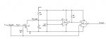
The attached schematic shows the circuit I used for the break detector. You could possibly use a diode OR gate instead of the 74LS32, but I had another use planned for that IC in the overall circuit, so I decided to use that.
The basic idea is that when the serial in is high, Q1 grounds C1, then when the serial in goes low, the capacitor charges (I needed R6 because the low output of the MAX485 is sometimes just over the base threshold of Q1 so I got some leakage through that for a start). By adjusting the pot (R4) you can get it so that the comparator causes a high signal after the serial in has been low for 48uS (indicating a break, rather than a 0 data byte), then that stays high until just after the break ends. The comparator output can go to a hardware interrupt pin (to detect a rising edge) and is ORed with the serial to make the break shorter and the mark longer
Hopefully this would give enough time for the PICAXE to get ready for the incoming data which follows
Attachments
-
 23.1 KB Views: 22
Last edited: