Solar Mike
New Member
I need a cell balancer for a three separate 48 volt banks of 8 series 6v lead carbon batteries; these are 300 AH sealed gel batteries and are proving difficult to get 100% balanced; once in a balanced condition, they will probably remain in that state and require little intervention.
Another requirement is to measure each individual cells voltage and raise some sort of alarm if any drop or go above set limits.
A simple balancing solution would have a voltage reference and voltage comparator attached to each cell, turning on a resistive load of several amps via a mosfet switch whenever the cells voltage went above a set point (7v in this case). Once the battery bank is near fully charged to 56 volts the charge current is only 1-2 amps, so it doesn't take much of a load on any runner cells to prevent them over charging.
Perhaps a 08M2 would do the job here, measure the cell voltage, turn on a mosfet, communicate with a Master Manager via opto-couplers, means using lots of cpu's but they are not that expensive compared to the $700 cost of each 6v battery.
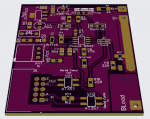
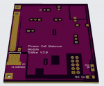
Here is my initial schematic, uses all smd devices to keep the pcb size down, each one fits onto a 50x62mm pcb designed to fit vertically across the resistor bank mounted on a heatsink. They are linked together via 10 pin ribbon IDC back to the master (yet to be designed), however each can be setup to run stand alone initially.

Note each cpu board sits at various battery cell potentials, so have to be initially programmed in a test jig prior, I imagine once a Master is connected it could alter voltage set points from a central point.
Will post the pcb soon...
Cheers
Mike
Another requirement is to measure each individual cells voltage and raise some sort of alarm if any drop or go above set limits.
A simple balancing solution would have a voltage reference and voltage comparator attached to each cell, turning on a resistive load of several amps via a mosfet switch whenever the cells voltage went above a set point (7v in this case). Once the battery bank is near fully charged to 56 volts the charge current is only 1-2 amps, so it doesn't take much of a load on any runner cells to prevent them over charging.
Perhaps a 08M2 would do the job here, measure the cell voltage, turn on a mosfet, communicate with a Master Manager via opto-couplers, means using lots of cpu's but they are not that expensive compared to the $700 cost of each 6v battery.
Here is my initial schematic, uses all smd devices to keep the pcb size down, each one fits onto a 50x62mm pcb designed to fit vertically across the resistor bank mounted on a heatsink. They are linked together via 10 pin ribbon IDC back to the master (yet to be designed), however each can be setup to run stand alone initially.

Note each cpu board sits at various battery cell potentials, so have to be initially programmed in a test jig prior, I imagine once a Master is connected it could alter voltage set points from a central point.
Will post the pcb soon...
Cheers
Mike
Last edited:


