Motorcycle Ignition using PICAXE18M2

PeterMooney

New Member
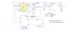
I'm trying to replace an old points based motorcycle ignition by using Hall effect trigger and PICAXE18M2 to provide variable advance/retard intervals. I have tried "pulsein" and "pauseus" hoping to get intervals of about 0.12 milliseconds but the interpreted Basic on the chip seems to be way to slow - taking half a second to respond.
Can't the 18M2 manage these millisecond response speeds?

Here's a snippet of code...
/*code*/
main:

pulsin c.7,1,w1 ; look for pickup low to high transition and store time in w1
;now check this time interval against the retard table...
;if no high to low transition or longer than 0.64 second then w1=0

select w1
case = 0 ;rpm < 500 so full retard 36 degrees
retardDelay = 12000 ;36 degrees
case < 7317 ;rpm > 4100 so full advance
; do nothing go make spark
retardDelay = 0
case < 7895 ;rpm > 3800 so delay 0.132 millisecs
retardDelay = 132 ; 3 degrees
case < 8571 ;rpm > 3500 so delay 0.286 millisecs
retardDelay = 286 ; 6 degrees
case < 9375 ;rpm > 3200 so delay 0.469 millisecs
retardDelay = 469 ; 9 degrees
case < 10345;rpm > 2900 so delay 0.690 millisecs
retardDelay = 690 ; 12 degrees
case < 11538;rpm > 2600 so delay 962 millisecs
retardDelay = 962 ; 15 degrees
case < 13043;rpm > 2300 so delay 1.304 millisecs
retardDelay = 1304 ; 18 degrees
case < 15000;rpm > 2000 so delay 1.750 millisecs
retardDelay = 1750 ; 21 degrees
case < 17647;rpm > 1700 so delay 2.353 millisecs
retardDelay = 2353 ; 24 degrees
case < 21429;rpm > 1400 so delay 3.214 millisecs
retardDelay = 3214 ; 27 degrees
case < 27273;rpm > 1100 so delay 4.545 millisecs
retardDelay = 4545 ; 30 degrees
case < 37500;rpm > 800 so delay 6.875 millisecs
retardDelay = 6875 ; 33 degrees
else ; rpm < 800 so delay 12.000 millisecs
retardDelay = 12000 ;36 degrees
end select

pauseus retardDelay

makeSpark:
;now make_spark
;break LT circuit
high B.0

'delay for dwell
if w1 = 0 then
dwellLength = retardDelay
else
dwellLength = w1/2 ;1/4 revolution (90 degrees)
endif
pauseus dwellLength

low B.0 ; close LT circuit again

goto main

/*code */

Where am I going wrong?
 

Goeytex

Senior Member
Ignitions are tricky using a Picaxe due to processor overhead and the limitation
of numbers no greater than 65535.

When the magnet on the flywheel passes the hall sensor a pulse is generated.
You now have the time between pulses to process the data and do something
before the next pulse comes. Since Pulsin is a blocking command no data can
processed while it is measuring the pulse. So be sure you are measuring the
the time the magnet is activating the hall sensor and not the time it is away
from the Hall sensor.

You also need to calculate the "duty cycle" by testing with pulsin measuring the
on time and then again measuring the off time. This relationship will not change
over RPM. Doing this the "Period" and or relative speed be calculated by only
measuring the shorter of the two. The less calculations the Picaxe has to
do on the fly the better.

The firing point BTC will be a moving target as the processor overhead is fixed but RPM
changes so a relatively advanced algorithm will be needed to compensate for processor
overhead to get the dwell and firing point correct. Otherwise you will burn up coils with
too much dwell and timing will be terrible over the RPM range.

Consider that a 10 us timing error at 500 PRMs is less than 1 degree, but at 8,000 rpms
is many degrees.

A Capacitive discharge ignition would be much easier to do with a Picaxe since there is no
dwell angle to compensate for.
 
Last edited:

hippy

Ex-Staff (retired)
Welcome to the PICAXE forum.

The PICAXE is an interpretive system so execution will be slower than native instruction execution but that can be offset by running at higher speeds, 32MHz for M2 and 64MHz for X2's ( see SETFREQ ).

The biggest challenge will be in delaying from a pulse to doing something just a 100us or so later. You have to calculate all that you need to determine the delay and complete it within those few microseconds. With PICAXE instructions around 30us for the simplest at 64MHz you don't have a lot of scope to do very much in that time.

It may be possible to read the pulse in one cycle and determine the retardation for the next time round but that would need multiple PICAXE to handle it alternatively, or perhaps use two; one to read the pulse and determine retardation, another told what retardation will be so it can deliver that as required. It's not a simple challenge.
 

PeterMooney

New Member
Thanks guys, I knew it might be tricky but I had calculated the necessary dwell and retard delays by spreadsheet. The issue was about getting the PICAXE interpreter to react quickly enough. I tried spotting pickup pulse on two revolutions using an interrupt, and timing the interval between two pulses but that was too slow too. I guess I have to go for an analogue solution instead.
 

bluejets

Senior Member

Goeytex

Senior Member
Picaxe CDI Ignition.

I have used the LT3750 to make some big sparks on the bench but have not actually
integrated everything into a complete ignition system.

The Picaxe sends a signal to tell the LT3750/52 to begin charging the cap. When the cap reaches a voltage determined
by the charge coil turns ratio and resistor RGB, the DONE signal goes low telling the Picaxe that the cap is
fully s charged to 320V.

When the hall sensor passes the magnet an interrupt is triggered which starts a delay. After that delay (the timing curve)
the coil is fired. The process repeats.

There is a bit more to the code such as sensing speed, but it should be doable with a fairly small program and very
few "IF" statements.

WARNING. HIGH VOLTAGES CAN CAUSE SEVERE INJURY OR EVEN DEATH.
 

Attachments

Last edited:

PeterMooney

New Member
Here's my basic circuit

View attachment Ignition Module.bmp

Thanks for the links. However I will only be using the existing motorcycle coil to generate the spark and use the PIC to replace the 40 year old advance/retard unit. This is my basic circuit - using a power MOSFET to fire the coil and a Hall effect or inductor pickup. The PICAXE will be used to add the appropriate retard delay and dwell angle according to the rpm. Typical retard will be 36 degrees (0.012 secs) at 500 rpm and decrease linearly to zero from 4000 up to the 10,000rpm limit.

I'm working with the PICAXE18M2 on a breadboard driving an LED and using a 555 timer to generate pulses at the moment. I didn't seem to be able to get fast enough reponses from the PIC - whether using an interrupt or pulsein commands.
 

hippy

Ex-Staff (retired)
I didn't seem to be able to get fast enough reponses from the PIC - whether using an interrupt or pulsein commands.
Perhaps post a short description of your program's theory of operation and the code you are using and then it will be easier to comment on what you have. The first suggestion will be to use SETFREQ to run at the fastest speed possible if you are not already doing that.

If you don't have past PICAXE or programming experience then coding for fast responses and low latency can be difficult and it's not always easy with experience.
 

MartinM57

Moderator
I can't understand (as you haven't given any great clues) how the sensor works. If you're programatically controlling the dwell angle (aka coil charging time) and the firing the coil at the right time before TDC (aka the advance position) then you need to know where TDC is physically and do the maths in the time domain depending on the rpm.

This is normally done with a typically 36-1 trigger wheel ie one tooth every 10 degrees and there is a missing tooth at some position relative to TDC (normally 90 degrees) - and a VR sensor feeding into a hardware chip that detects the missing tooth (forgotten the part #) which then forces an interrupt into the processor.

The maths required is not PICAXE execution speed friendly - you have to determine the rpm (not too hard) but then start counting/timing the teeth and inter-teeth gaps (making an assumption that the engine does not change speed between the teeth) to determine the coil on/off times e.g.

Interrupt fires at missing tooth (which is at 90 degrees BTDC)...and in the interrupt "immediately" (ie very very quickly)
From the last time it fired you can work out the RPM (you have to have an elapsed time timer running)
Lookup the advance and dwell time for that rpm (say 10 and 45 respectively)
So you need to schedule turning on the FET in 3.5 teeth time (i.e. 55 BTDC) and turn it off in 8 teeth time (i.e 10 BTDC)

The scheduling can be done in a number of ways, but again are not PICAXE friendly (high speed timers with very small resolution and interrupt routines that are fired immediately and run in "no time at all")

Also is the IRF540 Vdss at 100V enough? I'd be looking at more like 350V Vdss for safety, which takes you into specialised devices like VB921 etc

Or are you massively simplifying lots of things here?

(when I say "normally done" then I mean in the Megasquirt/EDIS sort of way e.g. http://www.megamanual.com/ms2/wheel.htm)
 

Goeytex

Senior Member
Peter,

The MOSFET is a poor choice for an ignition system. Your best bet is an automotive IGBT designed to fire modern "coil on plug" ignitions. These are hard to find in low quantities but look up the NGD8201N by ON Semi. In stock at Digikey. This is a logic level device that is clamped at 400v and is used by Auto Mfgs in modern ignitions. After you fry a few Mosfets you will appreciate one of these.

Programming the code for single sensor ignition as you have drawn up will be difficult to say the least. You will have to:

1. Detect speed ( relative, don't bother concerting to RPM as it is not necessary and wastes processor time )
2. Compute time period ( Relative)
3. Compute Firing position ( timing)
4. Compensate for Processor Overhead
5.Delay
6. Start Charging coil for it rated saturation time.
7. Immediately Fire Plug

You have less than 6ms to do this at 10,000 Rpm. That's not room for much code. So you code needs to be very tight
No long lists of "if thens" but rather two or three lines of math that do it all. Did you pay attention in algebra class?

Consider that at 1000 rpm the time period of 1 engine revolution is 60ms. So if your pulse is 10ms then
you have 54ms left, and if you start charging the coil right away it will go into saturation for about 40 - 50ms
(depending upon the coil) ... over heat and fail rather quickly.


Good Luck


3. Delay
4. Start charging Coil
 
Top