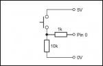
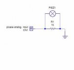
This circuit should get you moving in the right direction:
A piezo is very much like a capacitor. In the above circuit, R1 should be a preset POT included on the circuit board and should be adjusted to the point where the transistor just starts to conduct (the collector voltage just starts to drop from the +V rail voltage). A fixed resistor would be better, but that would require a particular transistor. Using the POT, you can adjust it for any transistor you have handy. C1 is a negative feedback capacitor, there to ‘roll off’ the frequency response, so that the sensor is less sensitive to higher frequencies. You don’t want it to respond to sounds do you? The value of C1 shown here is just a quick guess. Try different values until your sensor responds to vibration but not to sound.
The piezo disk will need a little mod. Glue one edge to your project (or window frame or dog), fix a bolt to the other edge like this:
The weight on the head of the bolt will cause a twisting or bending force depending on the direction of movement, but it will respond to movements in any direction.
Make sure that:
A) The edge you glue to the project is opposite from the bolt. In the above diagram, that would be near the point where the leads meet the piezo disk.
B) The rest of the disk (and the bolt) are not touching anything and are free to move/flex.
")