Mosfet / Transistor circuit help

Hi guys.

I am having trouble understanding how to impliment a mosfet and transistor in the way that I need, and am hoping someone could help me out with this really simple problem.
I havent taken any pictures of an actual circuit yet because this is a "How am I supposed to make this circuit" question, and not a "Here is my circuit which I know is supposed to work but is not".
Let me explain.

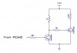
I have a varying voltage that is varying from 0-12v. this is being controlled by a varying 0-4v dc to tip102 darlington transistor circuit as seen in image 1 of the attachement.
This is working perfectly. I have it connected to a 12v led strip and it fades with the signal perfectly.

I have another circuit, image 2, that uses a mosfet (irfp250) to fade much bigger lights. It is being sent a varying 0-12v signal (NOT from the first circuit), and it works perfectly.

So I am trying to figure out how to get varying 0-12v from the first circuit to feed into the gate and control the second circuit. However I am not sure how to do this because the output of the darlington transistor is connected to the anode of the load, and the cathode of the load is to common +ve. Where as I think I need it the other way to control the mosfet (the anode of the load is connected to common ground and the cathode is connected to the transistor.) I have tried this arrangement (image 3) but it does not work in the same way the first circuit does in fading the 12v led strip, and I am not sure why (I think the internal diode?).

So yeah all I want to do is use my varying 0-12v circuit from image 1 to modulate the mosfet from image 2.

I am sure this is a really easy problem to solve, I just do not have as good of an understanding of transistors and mosfets as I would like.
Any guidance would be very appreciated. Thank you!

PICTURE ATTACHEMENT:
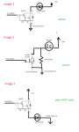
 Untitled.png
 

geoff07

Senior Member
Image 3 does not work because the load is in the emitter circuit and the load voltage offsets the drive voltage. An led drops at least 2v and maybe more depending on colour, which cancels out much of your drive voltage.The other cases are collector or drain loads and do not affect the drive voltage.

You may want to consider another approach using PWM, which would be a more common approach on this Picaxe forum (as you would be able to use a Picaxe to do it). By altering the drive to dim the lamps you are dissipating a lot of energy in the transistor. The PWM approach flashes the lamp at high frequency. The mark/space ratio determines the brightness. Because the transistor is always full on or fully off, it dissipates little heat. This will work more linearly as low intensities will not be affected by the 'knee' in the led curve. It can still be voltage controlled but would not need such a big heatsink or a complex transistor type. A mosfet with a logic-level drive would be perfect.
 

Billo

Senior Member
Circuit 3 will not work because the voltage drop across the 12V LED strip will prevent the BE junction of the Darlington from forward biasing.

As suggested, consider using PWM and a circuit like the attached.

PWM Lamp Driver.jpg
 

Paix

Senior Member
Is this not a satisfactory solution to connect to a PWM pin on a Picaxe?

Logic Level FET

Code:
                 +24V
                  |
                 LOAD
                  |
               |--+
o---1k ---+----| Logic Level FET
          |    |--+
         10k      |
          |       |
         Gnd     Gnd
 
I am trying this circuit now. The ultimate plan was to use pwm from the picaxe to control the lights. Sometimes I forget that pwm and varying voltage is different
i'll let you know how the circuit goes. thanks
 

rossko57

Senior Member
PWM for a 200V 30A load is going to be a bit more exciting than for 12V LEDs, circuit design at these levels is not to be taken lightly. Effects that are minor at 12V/1A become significant at the higher power. Trial-and-error design will quickly fry everything.

Is this a mains power project? 200V DC is a bit unusual ; but if you are switching AC then completely different techniques are needed.
 
yes I am using a rectified 120v dc to power the lights and it is modulated by the irfp250 which is being sent a 0-12v audio signal. It works perfectly. I have lamps fading perfectly with music. However I am using a stereo system to provide the 0-12v. I have my other circuit which is fading 12v leds in the exact same way being amplified from the audio jack. Now all I need to do is get the 2 circuits working with eachother so I no longer need to use the stereo system. The signal will go through a picaxe so that it is pwm later, but for now I just need to get this part of the circuit working without using a picaxe. The circuit posted above does not work in the way that I need it because I need the irfp250 to modulate 120v dc and not 24v dc.
 
Hi! I just discovered this mosfet FQB34N20L
can someone please confirm if this would work???
I need to fade 120v 10a dc with the mosfet. Will the picaxe be able to simply pwm out to the gate of this?
It says its logic level in the datasheet but I just wanted to make sure
 
I also discovered this mosfet
which I think will also work in the same way but is the TO 220-3 package size that would work much better.

Can someone let me know if they think this will work before I order it? Thank you!
 

rq3

Senior Member
I also discovered this mosfet
which I think will also work in the same way but is the TO 220-3 package size that would work much better.

Can someone let me know if they think this will work before I order it? Thank you!
This is not a logic level MOSFET, and won't turn on fully when driven by a PICAXE. When in doubt, look at the Rds spec in the device data sheet. The small print will specify the gate voltage (in this case, 10V).
 

Paix

Senior Member
@Plasmaninja, you have to admit that prior to my thoughts on the matter, there was no mention of high voltages and given that 100V @40A was one of the option devices suggested, I think that my crystal ball must have a New Year induced intermittent fault? Perhaps even a flash-over, caused by drinking too much Corona pop as a kid I guess . . .

Gate Threshold voltage of the FQB34N20L is between 1 and 2V min and max at 250uA.
yes i forgot to mention that sorry. So this FET will do the trick then? I am just wondering about the package size. D2PAK seems pretty small and I am expecting this thing to get pretty hot and need to be heat sinked when running at roughly 10 amps.
 

bluejets

Senior Member
You could parallel a couple of the above.
Depends on pwm frequency as to the total wattage.
Others more experienced may be able to give you some figures.
 

lbenson

Senior Member
I'm not that more experienced person, but I would guess that in addition to raising safety concerns about proper isolation with that voltage and current, you would be told that you cannot expect to pwm such a power mosfet directly from the picaxe without a proper driver, without which you are likely to fry the mosfet at a minimum, and possibly your circuit and yourself.
 
Top