Measuring pulsewidth > 655.36 ms ??

Hydroid

Senior Member
Hi,

I purchased a WWVB module (http://www.pvelectronics.co.uk/index.php?main_page=product_info&cPath=9&products_id=7) to experiment with the NIST time signal sent out from the WWVB transmitter near Fort Collins Colorado. I have a La Crosse analog clock that receives its time from that transmitter, so although I live in Canada, I know I can receive the signal.

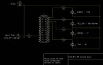
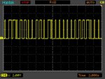
I hooked up the module and had to wait until about 8pm (local time) here, but I started to get the signal as evidenced from the onboard LED. I also hooked it up to my scope and was able to see a nice clean signal that exactly followed the format given by the WWVB website (http://tf.nist.gov/stations/wwvbtimecode.htm). With a little practice, I was able to decode the pulses as seen on my scope, by eye, and convert the bits to read out the information (to prove to myself that I was getting valid data).

So, next step was to try and get a Picaxe chip to read/convert the data. I figured that since the format diagram shows that at the top of the minute there are two 800 ms pulses separated by a 200 ms gap, I could have the Picaxe watch the incomming pulses using PULSIN until it saw that combination (Two 800 ms pulses in a row). That's when my idea fell apart as I soon figured out that at the lowest possible frequency (4 MHz) the PULSIN value of 10 us means I can only read a pulse of up to 655.36 ms.... :(

So, is there a way I can check reliably for a 800 ms pulse ?

I see from my searches that people have gotten the decoding the NPL MSF time signal, but it appears to use a maximum pulse width of 500 ms which can be handled by PULSIN.

Has anyone been able to use a Picaxe to decode the US WWVB signal ??

Thanks, John.
 

nick12ab

Senior Member
"lowest possible frequency (4 MHz)" - Which PICAXE are you using? All modern PICAXEs also support 2MHz and 1MHz operation as well. See the setfreq command in PICAXE Manual 2.
 

Goeytex

Senior Member
Hi John,

You can use <setfreq m2> to set the processor to 2 mHz. At 2mHz 1 pulsin unit will equal 20us giving a max of 1,310,700 ms
before timing out.
 

Hydroid

Senior Member
When I say "Lowest possible frequency", I am referring to the 4 MHz that's listed in the manual under the PULSIN command (Section 2, Page 160), which I did review.

I wasn't aware that some chips could run slower than 4 MHz - Good to know, thanks.

The PULSIN page only mentions effects of increased clock speeds starting at 4 MHz and going up. Are you saying that reducing to below 4 MHz would allow larger measurement units and the ability to measure wider pulses than 655 ms ?
 

Hydroid

Senior Member
Thanks Goeytex - I was responding to the previous message and posted it while you were replying to mine.

I'll give the speed reduction a try.

Thanks to both of you for replying.

Very helpful forum !

John.
 

hippy

Ex-Staff (retired)
Or do the 800ms pulse detection by polling. The following code will either abort from within the loop if a high pulse goes low before 800ms or exit the loop when present for at least 800ms. You'll have to tweak w0 to create the 800ms timing ...

Do : Loop Until PinX = 1
w0 = ?
Do
If pinX = 0 Goto ThisIsNotThe800msSyncYouWereLookingFor
w0 = w0 - 1
Loop Until w0 = 0
Goto GotThe800msSync
 

g6ejd

Senior Member
The best way to decode these time signals is by detecting the edges, because they are the time references not the pulse durations.

Wait for the first edge, delay half a bit time, then take a data reading, then wait for the next edge. Something like:

Receivebit:
If receiverinput = 0 then goto receivebit
Pause halfbittime
Databit = pin port.pin
Return

Doing it this way removes the need. Also check the spec. As for sure it's the edges proving the references.

The advantage of doing it this way is that it gives you lots of time between pulses to do other things like display the characters convert bytes to day of week, or whatever. The best solution would be to have the picaxe be interrupted when the edges occurred and receive the data in the background while the foreground task displayed the results, either way works well.
 

Hydroid

Senior Member
SUCCESS !! (So far...)

The best way to decode these time signals is by detecting the edges, because they are the time references not the pulse durations.
I think that's true for the MSF signal (Cambria, UK) if I read the description correctly (http://en.wikipedia.org/wiki/Time_from_NPL), but for the signal I'm receiving, WWVB (Colorado, USA), pulse width definitely signifies values: Double 800ms pulses followed by 200ms pulse = Top of Minute marker, 800ms pulse followed by 200ms pulse = 10s markers, 500ms pulses = logical '1' and 200 ms pulses = logical '0' (http://tf.nist.gov/stations/wwvbtimecode.htm).

I like the fact that the MSF signal encodes the date by giving Day, Month and Year whereas the WWVB only gives Days (# of days passed since 01 Jan) and Year - Requires a little math to arrive at the correct Month and Date. The WWVB also encodes 'leap second' notification, which I don't see in the MSF signal...

After the assistance received regarding lowering frequency to 2MHz to allow a PULSIN value of 20us (Note: would be a nice edit if the PULSIN description in the manual stated this), I was able to use PULSIN to achieve my desired results.

I breadboarded the circuit (attached DSN), and uploaded the code to the 28X1

Code:
# picaxe 28x1

#rem

Demo program to 'read-in' pulses from output of SYM-RFT-60 WWVB decoder board and light up one of four LEDs representing:

- TOM (top of minute marker)
- Marker (10 s marker)
- logical '1'
- logical '0'


-location assignments:

	w0 = pulsin value
	w1 = 2nd pulsin value (used to detect if TOM found)


-pin connections:

	1 = RESET switch
	2 = N/C
	3 = N/C
	4 = N/C
	5 = N/C
	6 = Prgm plug Serial in
	7 = Prgm plug Serial out
	8 = 0 volts (-ve)
	9 = N/C
	10 = N/C
	11 = in0 - from SYM-RFT-60 TCON pin
	12 = N/C
	13 = N/C
	14 = N/C
	15 = N/C
	16 = N/C
	17 = N/C
	18 = N/C
	19 = N/C
	20 = 5 volts (+ve)
	21 = N/C
	22 = N/C
	23 = N/C
	24 = N/C
	25 = out4 - red LED (logical '0')
	26 = out5 - green LED (logical '1')
	27 = out6 - yellow LED (10 second marker)
	28 = out7 - amber LED (TOM = top of minute)

#endrem


	setfreq m2						'set frequency to 2 MHz to give a pulsin period of 20 us to allow checking
								'for pulse width of up to 1.31072 seconds (65536 count at 20 us each)
	
	dirsc = %00000000					'set all portc pins to inputs
	
	symbol AMBER = 7					'amber LED on output 7				
	
	symbol YELLOW = 6					'yellow LED on output 6
	
	symbol GREEN = 5					'green LED on output 5
	
	symbol RED = 4					'red LED on output 4
	
	
	pulsout AMBER, 10000				'200 ms pulse on LEDs as test at start of program
	pulsout YELLOW, 10000
	pulsout GREEN, 10000
	pulsout RED, 10000


main:

	pulsin 0, 1, w0					'read pulse width value into w0
	
	
	if w0 > 35000 then				'if 800 ms pulse (>700 ms)
	
		pulsin 0, 1, w1				'read next pulse into w1. If not at TOM, then this will get rid of 200 ms pulse following a marker
		
			if w1 > 35000 then		'if 2nd pulse is 800 ms (>700 ms), then TOM found
			
				pulsout AMBER, 10000	'signal TOM marker
				
				pulsin 0, 1, w0		'extra pulsin to get rid of 200 ms pulse following TOM (double 800 ms pulses)
				
				goto main
				
			endif
	
		pulsout YELLOW, 10000			'800 ms pulse (>700 ms) - 10 s marker found
		
		goto main		
				
	endif


	if w0 > 20000 then				'500 ms pulse (>400 ms) - logical '1'
	
		pulsout GREEN, 10000
		
		goto main
			
	endif


	if w0 > 5000 then					'200 ms pulse (>100 ms) - logical '0'
	
		pulsout RED, 10000
		
	endif


	goto main
I had to wait until about midnight (local time) for the signal to become clean (as expected from the description on the WWVB pages - which is why they state that radio controlled clocks are usually programmed to update somewhere around 1-3 am), but once the signal had no noise, the circuit worked perfectly.

Amazing how much joy one can take in watching 4 LEDs blink in the wee hours of the morning !! :D (I was up until almost 0300 !)

This morning, related my success to the Mrs. and was greeted with a puzzled "So What" look.... Just doesn't "Get it" I guess :)

Thanks again for all your help guys ! Comments welcome, but remember this is a 1st attempt... Be gentle :)

Now, to begin writing some code to convert blinking LEDs to meaningful data.

I think I'll start by building a quicky circuit to 'simulate' the pulse train so I can do some coding during the day - easier on the brain cells !
 

Attachments

Hydroid

Senior Member
Sorry, not sure how to save a schematic as a JPG (no option for that).

Took a screen shot and cropped it to a JPG. Hopefully, it's visible for you.
 

Attachments

Hydroid

Senior Member
Argghh

Just when you think you've got it licked....

Put together a 08M2 to provide simulated pulses into my WWVB decoder 28X1...

Knew something was amiss when I was only seeing 8 pulses between the 10 second markers - There should be 9 in all 10s segments except the first (In the first there are only 8 because the segment starts and ends with a 800ms pulse). Didn't notice this last night, be it the late hour or the false excitement in thinking I'd succeeded.

Looked over my code again, and the WWVB signal format sheet, and realized that I'd mis-read the sheet. The start of a 10s segment ISN'T identified by a 800ms pulse followed by a 200ms pulse... It's actually the end of a 10s segment that's identified by a single 800 ms pulse. Each 10s segment, except the first, starts with a 200ms or 500 ms pulse depending on whether the bit being represented is a 0 or a 1. The first 10s segment, starts and ends with a 800ms pulse, so that at rollover of a minute, you see two 800ms pulses in a row - this is the only place that that occurs. So my original code, which was 'throwing' away the bit following the 800ms pulse, was actually discarding a useful bit due to my misunderstanding the format.

My recode:

Code:
# picaxe 28x1

#rem

Demo program to 'read-in' pulses from output of SYM-RFT-60 WWVB decoder board and light up one of four LEDs representing:

- TOM (top of minute marker)
- Marker (10 s marker)
- logical '1'
- logical '0'


-location assignments:

	w0 = pulsin value
	w1 = 2nd pulsin value (used to detect if TOM found)


-pin connections:

	1 = RESET switch
	2 = N/C
	3 = N/C
	4 = N/C
	5 = N/C
	6 = Prgm plug Serial in
	7 = Prgm plug Serial out
	8 = 0 volts (-ve)
	9 = N/C
	10 = N/C
	11 = in0 - from SYM-RFT-60 TCON pin
	12 = N/C
	13 = N/C
	14 = N/C
	15 = N/C
	16 = N/C
	17 = N/C
	18 = N/C
	19 = N/C
	20 = 5 volts (+ve)
	21 = N/C
	22 = N/C
	23 = N/C
	24 = N/C
	25 = out4 - red LED (logical '0')
	26 = out5 - green LED (logical '1')
	27 = out6 - yellow LED (10 second marker)
	28 = out7 - amber LED (TOM = top of minute)
	
-REVS:R2: Code adjusted as initial code was incorrect. 800ms pulse signifies marker at end of 10s segment. Double 800 ms pulses signify TOM. Original code
	    was written assuming Marker was a 800ms pulse followed by a 200 ms pulse, which is not correct. Original code 'threw away' that 200 ms pulse - but in
	    some 10s segments, that represents data (ex 4th 10s seg where first bit represents 8 days).
	    
	R1: Original code.

#endrem


	setfreq m2						'set frequency to 2 MHz to give a pulsin period of 20 us to allow checking
								'for pulse width of up to 1.31072 seconds (65536 count at 20 us each)
	
	dirsc = %00000000					'set all portc pins to inputs
	
	symbol AMBER = 7					'amber LED on output 7				
	
	symbol YELLOW = 6					'yellow LED on output 6
	
	symbol GREEN = 5					'green LED on output 5
	
	symbol RED = 4					'red LED on output 4
	
	
	pulsout AMBER, 10000				'200 ms pulse on LEDs as test at start of program
	pulsout YELLOW, 10000
	pulsout GREEN, 10000
	pulsout RED, 10000


main:

	pulsin 0, 1, w0					'read pulse width value into w0
	
	
	if w0 > 35000 then				'if 800 ms pulse (>700 ms)
	
		pulsout YELLOW, 5000			'Marker found
	
		pulsin 0, 1, w1				'read next pulse into w1 to determin if at TOM.
		
			if w1 > 35000 then		'if 2nd pulse is also 800 ms (>700 ms), then TOM found
			
				pulsout AMBER, 5000	'signal TOM marker
				
				goto main
				
			endif
			
			if w1 > 20000 then		'next two steps pulse either GREEN or RED if TOM wasn't found so bit is not lost 
			
				pulsout GREEN, 5000
				
				goto main
				
			endif
			
			if w1 > 5000 then
			
				pulsout RED, 5000
				
				goto main
				
			endif
	
	endif


	if w0 > 20000 then				'500 ms pulse (>400 ms) - logical '1'
	
		pulsout GREEN, 5000
		
		goto main
			
	endif


	if w0 > 5000 then					'200 ms pulse (>100 ms) - logical '0'
	
		pulsout RED, 5000
		
	endif


	goto main
So now my 28X1 decodes the simulated stream perfectly - I've got the 'buggy eyes' to prove it :)

Of course, it's only a simulated signal. The real test comes tonight after midnight when I 'look' at the real WWVB signal - Keeping my fingers crossed !

Wouldn't be any fun if it were easy....
 

John West

Senior Member
John,
While I now live only about 40 miles from WWVB, I used to pick it up on a home-brew Tuned RF receiver when I lived in Michigan. In fact, my antenna was in my basement, but I had a good looking sine-wave at 60kHz with the amplitude modulation of the code bits very obvious. (BTW, I too used to sit up late at night staring at the waveform, but on my scope. It was more interesting than LED's.)

The two tricks to getting a good signal 24 hours a day are to have a good antenna, and to locate it and ground it as far as possible from electrical noise sources. Thus my basement antenna. Of course, outdoors, up in the air 8 or 10 feet would be better if you're allowed to locate such an antenna in such a location.

I used a large loop antenna, (about 3 ft in diameter with a couple hundred turns of wire,) carefully resonated to 60 kHz with an air-variable capacitor, to keep the Q high, carefully pointed for best observed (on the scope) signal to noise ratio, and an op-amp at the antenna to amplify the signal before it could pick up any noise as I fed it up to my lab.

Basically, about any antenna you can come up with, properly placed, will work better than the typical tiny loopstick antenna, (which I see from the picture of the product you purchased, you do indeed have,) found in most WWVB receivers.
 

Hydroid

Senior Member
Can you post your 'scope signals?
e
Took some doing as I don't use the scope that often, but a quick tour through the manual to refresh myself and:

wwvb.jpg

2s/div on the horz. allowed capture of about 24 seconds, while still allowing it to be read OK. I also captured the first two 10s time segments so the double marker (second 59 & 0) can be seen at the minute rollover. Decoding it gives:

1st 10s: M 0 1 1 0 0 1 1 0 M = 36 minutes

2nd 10s: 0 0 0 0 0 0 0 1 1 M = 3 hours

and the time here was 2236 hours (I'm in the Eastern Standard Time Zone) which is 0336 UTC :)

I watched a few minutes worth of data, and I now receive 8 data bits in the first 10s segment and 9 data bits in the other five 10s segments, which is correct. So it appears my code adjustment did the trick.

John.
 

Hydroid

Senior Member
(BTW, I too used to sit up late at night staring at the waveform, but on my scope. It was more interesting than LED's.)
Hi John,

Oh I have my scope hooked up too so I can compare the LED pulses with the scope pulses. I don't know why it seems so fascinating to watch, but it is...


The two tricks to getting a good signal 24 hours a day are to have a good antenna, and to locate it and ground it as far as possible from electrical noise sources....
I used a large loop antenna, (about 3 ft in diameter with a couple hundred turns of wire,) carefully resonated to 60 kHz with an air-variable capacitor, to keep the Q high, carefully pointed for best observed (on the scope) signal to noise ratio, and an op-amp at the antenna to amplify the signal before it could pick up any noise as I fed it up to my lab.
Basically, about any antenna you can come up with, properly placed, will work better than the typical tiny loopstick antenna, (which I see from the picture of the product you purchased, you do indeed have,) found in most WWVB receivers.
I live on an acre and a half, so room (or mounting at height) isn't an issue. Just have no idea about antenna's. Has always seemed mysterious to me and wouldn't know where to start.

Funny though that my La Crosse RC analog clock, which by looking at the back has the same size and type of antenna as my decoder setup, can sync itself even in the middle of the day - in about three minutes....

John.
 

John West

Senior Member
There are better (and worse) circuits available for such "clocks," and there's not always a significant price difference between them. That's why I recommended an outboard antenna. They always make such a circuit better. As for having "no idea about antennas," that's not much of a problem at this frequency. Just make a multi-turn loop of insulated wire that's a few feet in diameter, with the loops separated by at least the thickness of the wire, then connect a variable capacitor across the terminals and run the two leads to the same place your little ferrite loop goes to, instead of it.

The only trick is having enough inductance and capacitance on the antenna to resonate at 60 kHz. The easy way to do that is to built the loop, then put a few hundred Ohm resistor in one of the legs of the loop, then place a variable capacitor across the resistor end and loop end and feed that point with a signal generator of some sort that will vary in frequency, and keep adding paralleled capacitors and adjust the variable cap until you see the largest signal across the resistor connections at 60 kHz when viewed by a scope hooked across it. That's the resonant point, the point with the most sensitivity to 60 kHz.

If your variable capacitor isn't a high enough value to see a peak, you can parallel it with fixed capacitors until it is. Then tune the capacitor until you can tune above and below the functional data point with the pot. Then center it there and remove the resistor. Piece of cake. You can experiment all you want without doing any harm.

If you can measure the inductance of the loop you built with an inductance meter, you can then just select a capacitor with the same reactance at 60 kHz as the loop has inductive reactance at 60 kHz and you're in biz.

For further info on this, just look up "resonance," and LCR (inductive, capacitive, resistive) circuits, or "Loop antenna" design on the web. Loops are the most fun part of playing with WWVB reception circuits. And if you have a scope handy, they are very easy to figure out.

If you have further questions, you can PM me.
 

Hydroid

Senior Member
The easy way to do that is to built the loop, then put a few hundred Ohm resistor in one of the legs of the loop, then place a variable capacitor across the resistor end and loop end and feed that point with a signal generator of some sort that will vary in frequency, and keep adding paralleled capacitors and adjust the variable cap until you see the largest signal across the resistor connections at 60 kHz when viewed by a scope hooked across it. That's the resonant point, the point with the most sensitivity to 60 kHz.......

If you have further questions, you can PM me.
Thanks for your offer of assistance John,

After I get a few projects off the 'list' - including the 'honey do' list (Happy Wife = Happy Life!), I may give that a go.

I knew I had a signal generator around here somewhere that I picked up years ago. Just checked it: Marconi TF2016A - 10kHz-120MHz AM/FM signal generator.

If nothing else, it'll give me a reason to play around with that - and my frequency counter (which was bought at the same time). Will be able to prove my adage to the Mrs.: I bought them because 'Some day', I might need them :)

Regards, John.
 

Hydroid

Senior Member
Just for fun, on Sunday,
I ordered one of those modules you mentioned in post #1.

No way I can help with the WWWV however, :-(
the Tx is much too far away.

However, for Brits, the module and supplied antenna work very well.

I used Hippy's code from post #32 here:

http://www.picaxeforum.co.uk/showthread.php?11334-Decoding-UK-s-NPL-MSF-Time-Signal/page4&highlight=Argos

I just changed the "Restart" to "resstart".

e
e, Glad yours is working!

I've actually gotten mine working too. I've made a quicky breadboard and am reading in just the first 18 bits (to get the minutes & hours) and updating a 4 digit 7 Seg. display.

I have to wait until about midnight for the signal to become clean enough for it to be good, but it is updating the time perfectly - and repeatably.

As John West pointed out, a bigger external antenna would allow better reception. That has been added to the never ending 'to do' list.

Regards, John.
 

eclectic

Moderator
snip
I've actually gotten mine working too. I've made a quicky breadboard and am reading in just the first 18 bits (to get the minutes & hours) and updating a 4 digit 7 Seg. display.
snip
.

Can I suggest that you write it up as a mini-project?

We've already got MSF circuit and code basics on the Forum,
so a WWVB Picaxe primer could be useful for the Cousins. :)

e
 
Last edited:

Hydroid

Senior Member
Can I suggest that you write it up as a mini-project?

We've already got MSF circuit and code basics on the Forum,
so a WWVB Picaxe primer could be useful for the Cousins. :)

e
It's pretty rough right now, but once I get it working to my satisfaction, I can do that.

John.
 

nick12ab

Senior Member
Can anyone post a link to the MFS circuits on the forum?
I'd like to find an MFS time signal simulator, if such easily existed.
An MSF time signal simulator is possible on PICAXE.

Could you please start a new thread as this isn't related to this thread.
 
Top