Measuring frequency with internal timer

Janne

Senior Member
Hi,

I've hit a headscrather with my latest project. What I'm trying to do, is to measure the perioid of an AC voltage, to get the rotating speed of a windmill generator. The hardware for this is very simple, I just have an optocoupler connected with 2x 470k resistors in series and a reverse diode to the AC voltage. On the secondary side I have a 470k pullup resistor to +5V. The signal on the input pin looks nice, not square wave but should be good enough.

On the software I have an interrupt driver counting for the perioid. The timer is set for 512µS preload. I have 2 interrupts, one for low going edge and one for high going edge. The timer value is recorded and reset to 0 only on high going edge, so that the un-symmetrical triggering of the input should not matter.

I have this hardware plugged to 50Hz mains(with isolating transformer), but instead of the ~40 counts between high going edges i only get 31-32.

To add more to the confusion, I also tested the same thing with my MPPT controller hardware. It is essentially the same, but with lower value resistors connected to the optocoupler to make it work with my 12V rated wind turbine.
I hooked it up to the function generator, and sure enough, on small frequencies it seems to give values 20% too small. But between 60-80Hz something magical happens, and the error disappears. On 100Hz i get 19-20 counts, and on 150 i get 13-14, like I would expect. I also tried feeding the optocoupler with square wave to make for even better waveform, but it didn't do any good. I also tried removing the scratchpad averaging function, and inserted a pause between display updates, to make it readable. Same thing still.

The code snippet for the interrupt and timer setup;


Code:
#picaxe 28x1
SETFREQ EM16	

INTFLAG = INTONRISE
SETINT INTFLAG,INTMASK	'set interrupt on pin 2 being high
SETTIMER 65504		'set timer with 512µs preload
.
.
.

main function is used in the test just to update the LCD display to show the perioid

.
.
.

INTERRUPT:				'interrupt is used for calculating the time between zero crossings

IF INTFLAG = INTONFALL THEN	'this routine causes every other interrupt just to set the int again and return
					'triggered on the falling edge of the signal				
	INTFLAG = INTONRISE		
	SETINT INTFLAG,INTMASK		'set interrupt for raising edge again	
	RETURN
ENDIF

IF TIMER > 255 THEN
	@PTR = 255
ELSE
	@ptr = timer 		'AVERAGE WITH SCRATCHPAD
ENDIF
TIMER = 0
ptr  = ptr - 6
tempw2 = @ptrinc + @ptrinc + @ptrinc + @ptrinc + @ptrinc + @ptrinc + @ptrinc / 7
PERIOD = TEMPW2 MAX 255

INTFLAG = INTONFALL
SETINT INTFLAG,INTMASK		'ENABLE INTERRUPT AGAIN, THIS TIME ON LOW GOING EDGE

RETURN
Also, the full program code is attached below.
The picaxe in the "mains" version is 28x1 v6, and on the mppt hardware 40x1 v3.

Any help is appreciated.
 

Attachments

MartinM57

Moderator
Not looked at the code, and what you are doing in principle is fine (and a common technique)

However, I'd do it an easier way - just use the PULSIN command to measure the width of the pulse - resolution to 2.5us should be enough I would have thought....?
 

Janne

Senior Member
Hi,

I wanted to use the interrupt method to prevent the waveform from affecting the result.. To measure the time between raising edges.
Pulsin would work, if i could program it to read from 1st rising edge to the second rising edge.

If nothing else seems to work, then I guess i'll just make a correction table for the interrupt driven method, and go with it. It just doesn't make any sense to me, as in why it gives the faulty timing, with 2 different hardware.
 

hippy

Ex-Staff (retired)
Assuming the AC doesn't change drastically cycle from cycle, which it shouldn't, you can read tha low pulse, then read a high pulse and add them together to get the full cycle length. They won't be a consecutive cycle measurements but will only be one cycle apart.

Trying to use timer interrupts for high resolution measurement is fraught with difficulties as the PICAXE takes time to get into the routine with variable latency, and then it's a question of what are you timing; you reset timer=0 a considerable time after the interrupt. All those lost microseconds add up to inaccuracy.

The two best options are PULSIN ( two and add as described takes into account if it's not 50% duty ), or to COUNT how many cycles in a period, but that's not too convenient for lower frequencies.
 

MartinM57

Moderator
Surely the time between rising edges is just twice the time between a rising edge and a falling edge? PULSIN will measure rising to falling...

I just get nervous with PICAXEs when someone sets up timers for a few hundred uS with an EM16 frequency and observes odd results (each PICAXE instruction is taking about 100uS, so it's hardly surprising) - it's just a bit too close to comfort in terms of how fast the PICAXE code actually runs...fine on a 20Mhz AVR where a single cycle machine code instruction (and there's a lot of them) takes 50nS and you can change interrupt polarities so quickly (and run 1000 more instructions in those 500uS)

However, PULSIN will measue to 2.5uS with EM16 and if you had a 64Mhz PICAXE you'd be reading to 625nS which would seem good enough to me.

Up to you of course...
 

Janne

Senior Member
I understand that the timer functions in picaxe, combined with the polled interrupt has it's limitations.. But I though I would have been able to battle the variable latency with the scratchpad averaging. The delay between interrup call and resetting the timer, that should be (roughly) the same every time around, so it should not change the time it takes for the timer to be reset again. And what baffled me most, is that it was working correctly at higher frequencies. (And also that the recorded values were pretty much spot on 80% of the nominal value at lower frequencies throughout the range)

Anyways, the 2x pulsin commands with the values added sounds promising to me, I'll try that one next. The waveform is not symmetrical, so the time between rising and a falling edge is not half from the whole cycle.. The optocoupler with it's series resistors needs about 60V input to pull the picaxe input low.

Thanks again for all the help.
 

womai

Senior Member
I have done a lot of experiments with the Picaxe interrupts - trying to use them as trigger for a simple oscilloscope. What I found is that the interrupt latency changes by a bit over 1 Picaxe command period (which is ~0.5ms at 4 MHz), not surprising given that the interrupts are polled, i.e. the Basic interpreter only checks the interrupt condition after each Basic command. What was a bit surprising was that this holds true even when it executes a long "pause" statement (where according to the Picaxe manual the condition gets checked "continuously"). For a Picaxe 28X1 running at 16 MHz (what is what you seem to be doing) the latency could thus vary by about 0.15ms, which is 1.5% of a 50 Hz half period (10ms). Using the pulsin command should produce much better resolution (use Hippy's idea to mease high and low pulse separately); or if you can measure over longer periods (several seconds), count pulses (count command) over a given interval instead.

Wolfgang
 

hippy

Ex-Staff (retired)
What was a bit surprising was that this holds true even when it executes a long "pause" statement (where according to the Picaxe manual the condition gets checked "continuously").
That's possibly a mistake in confusing "continuously" with "continually" ( and I had to look it up to find which was which ) but I believe they are checked very frequently though it could be case of an inner and outer timing loop with polling in the outer but not in the inner. It could therefore depend on where/when in the inner loop the interrupt occurred.
 

SAborn

Senior Member
Hi Janne,

You might want to give Gordon a PM over on TBS as i know he has a system operating with what you are trying to do.
 

manuka

Senior Member
Janne:What exactly are you doing?You've not mentioned the size & rotational speeds, but I'll assume things are a few hundred Watts & hence a small turbine spinning quite rapidly.Why rotational speed need? What wind experience & resource do you have? Once you start on wind energy numerous other issues (electrical,mechanical,visual,acoustic & SAFETY) tend to arise, the least of which is often working high up on a tower. Ground level solar PV (if you have it- maybe a winter issue at your latitude) is usually spared such concerns!

It's not just rotational speed, but more the wind "run" that is of interest normally - implying PICAXE "count" may be your friend. However good use of cheap bike computers has been made for monitoring both instananeous generated current & also Amp hour accumulation. See => http://www.reuk.co.uk/Use-a-Cycle-Computer-to-Measure-Turbine-RPM.htm and => http://www.thebackshed.com/ etc etc

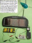
I've a simple early 2007 approach (below) that worked well-check details here .
 

Attachments

Last edited:

boriz

Senior Member
“What I'm trying to do, is to measure the perioid of an AC voltage, to get the rotating speed of a windmill generator.”

Seems to me like you’re doing it the hard way. Interrupts are polled between commands, so not only is there often little difference between an interrupt and a normal spontaneous test, once an interrupt has been started it slows the whole program down. I avoid them where possible.

What’s wrong with a simple COUNT command? The Period can be changed on the fly for different circumstances if needs be. Say, a longer period for lower RPM and a shorter period for higher RPM.

What’s the anticipated frequency range? And how accurate do you need it?

EG:
Code:
‘unoptimised for clarity
do
     Period=1000 ‘quarter of a second @ 16MHz
     COUNT pin,period,w0
     If w0<critical_value then
          Period=8000 ‘two seconds @ 16MHz
          COUNT pin,period,w0
     Endif
     Gosub display_RPM
loop
Where critical_value is determined beforehand based upon how accurate you need your low RPM count to be and what period delay is acceptable.
 

Janne

Senior Member
The project is to make a heating controller for an Exmork 3kW windmill. Basically, read the speed of the turbine, and use a lookup table to drive the pwm generator so the turbine gets loaded ideally and optimal rotational speed is maintained.
The generator has an over-voltage activated safeguard, so even if the controller goes dead, the turbine will not overspeed.

The working frequency is from 10Hz-35Hz, and I'd like to measure it with (at least)about 50 points resolution in the range. It could be possible to get away with less resolution, but I'd like to keep my options open.
A desired update rate for the pwm would be around 2 times / second, so the count command would not give a good enough resolution.. Hence the need to read the speed by measuring the perioid of the AC voltage.

I've been playing with windturbines for a while now, and built a couple of smaller ones, so the ins and outs of a windmill are familiar to me. It's the controller part that I'm having most trouble and fun right now.

ps. do i need to put a resistor betweend the picaxe output pin and the FETs driving the resistor bank? ;)
 

John West

Senior Member
I think this might be your problem:

"I just have an optocoupler connected with 2x 470k resistors in series and a reverse diode to the AC voltage."

What's the input current required to drive the opto? If your windmill sources only 12VAC nominally then the nearly 1M Ohm impedance placed in line will not turn on the opto coupler reliably - if at all.

Or did you mean 470 Ohms - a far more appropriate value.

A schematic of the input circuit would help. I'm a visual kinda guy. I get lost in circuit descriptions.
 
Last edited:
Top